Optical system generating a structured light field from an array of light sources by means of a refracting or reflecting light structuring element

a technology of structured light and structure elements, applied in semiconductor lasers, lighting and heating apparatus, instruments, etc., can solve the problems of too limited flexibility in designing a system to meet the requirements of the application in this way, and achieve the effect of reducing cost and increasing flexibility in design

Active Publication Date: 2015-12-10
IEE INT ELECTRONICS & ENG SA
View PDF5 Cites 140 Cited by
  • Summary
  • Abstract
  • Description
  • Claims
  • Application Information

AI Technical Summary

Benefits of technology

[0008]The disclosure provides an optical system which gives a larger flexibility to design the structured light field.
[0009]The present invention relates to an optical system which transforms the output of an array of light sources into a structured light illumination by collimating, deflecting or reflecting the light beam of each individual light source and thus directing each beam into the scene under vertical and horizontal angles that can be arbitrarily chosen. The freedom of choice of the spatial direction of each beam enables a high flexibility in the adaptation of the illumination to the particular requirements of an application regarding the distribution of light beams over the field of view. This can be achieved with standard low-cost light source arrays, not requiring complex arrangements of the individual light sources.
[0011]With the optical system according to the present invention, it is possible to produce a pattern in the illumination field of high radiance and contrast, even at a large distance from the illumination unit. The components of the optical system thereby ensure the collimation of the light beams of said light sources as well as the generation of an arbitrarily chosen light pattern for projection independently of the exact form of the original arrangement of said light sources within said array of light sources. The use of a structuring unit, which is preferably separate from said array of light sources, enables to shape the illumination field according to the application specific requirements. As the shape of the illumination field is determined by the configuration of the structuring unit, it will be appreciated that for a given arrangement of the light sources, it will be possible to change the shape of the illumination field by replacing the structuring unit.
[0019]The optical system enables the realization of spatial coding methods in the structured light field with more freedom and gives a larger flexibility to design the structured light field according to the requirements of the application regarding FOV, distribution of the graininess of the structured light field over the FOV as well as the range of distances over which the system should function as a function of the angles spanning the FOV. This is even easily achieved when the illumination generator is based on an array of light sources arranged in a regular pattern.
[0021]Using arrays of light sources of high radiance the optical system described by the present invention allows for the generation of a structured light field, which can be tailored to fill a given FOV and to follow the distributions of graininess and intensity as required by the application, without loss of radiance. Furthermore, the invention provides an increased flexibility in the design of the structured light field for applications requiring an illumination of large radiance, while reducing cost as compared to other methods. For example, the possibility to use a regular light source arrangement (densely packed) leads to the best use of expensive substrate material.

Problems solved by technology

The challenge with this type of illumination unit is to distribute the individual light sources in such a way on a given chip area, that the pattern of the positions of the light sources in any given subarea of the chip area is unique.
However, for cost reasons, and because of diverse technical limitations the size of such an array of light sources and the freedom to arrange the light sources within the array is limited, such that the flexibility to design a system to the requirements of the application in this way is too limited.

Method used


Image

  • Optical system generating a structured light field from an array of light sources by means of a refracting or reflecting light structuring element
  • Optical system generating a structured light field from an array of light sources by means of a refracting or reflecting light structuring element
  • Optical system generating a structured light field from an array of light sources by means of a refracting or reflecting light structuring element

Examples


Embodiment Construction

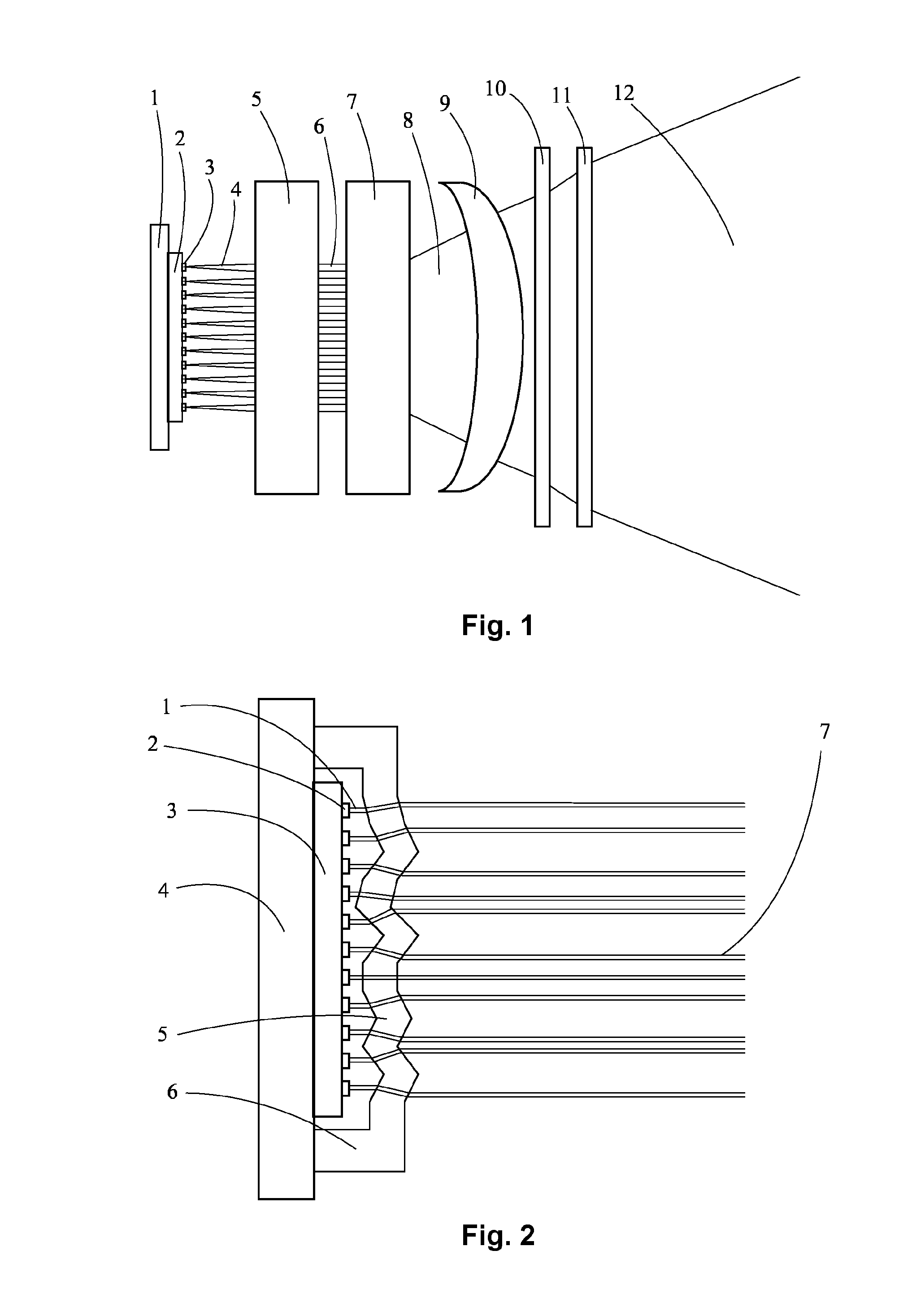
[0032]Prior to describing details of several possible realizations of the invention, an overview of a general setup of the illuminator is given. A structured light illumination generator using the present invention will have a general construction as schematically shown in FIG. 1.

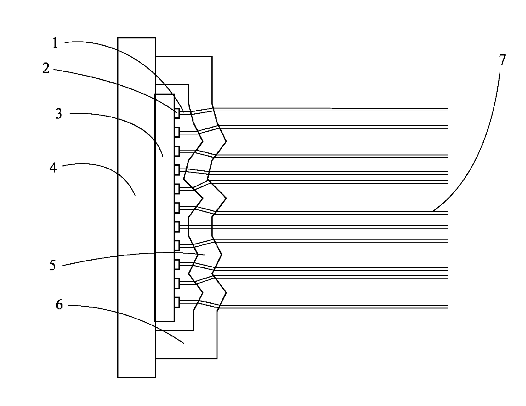
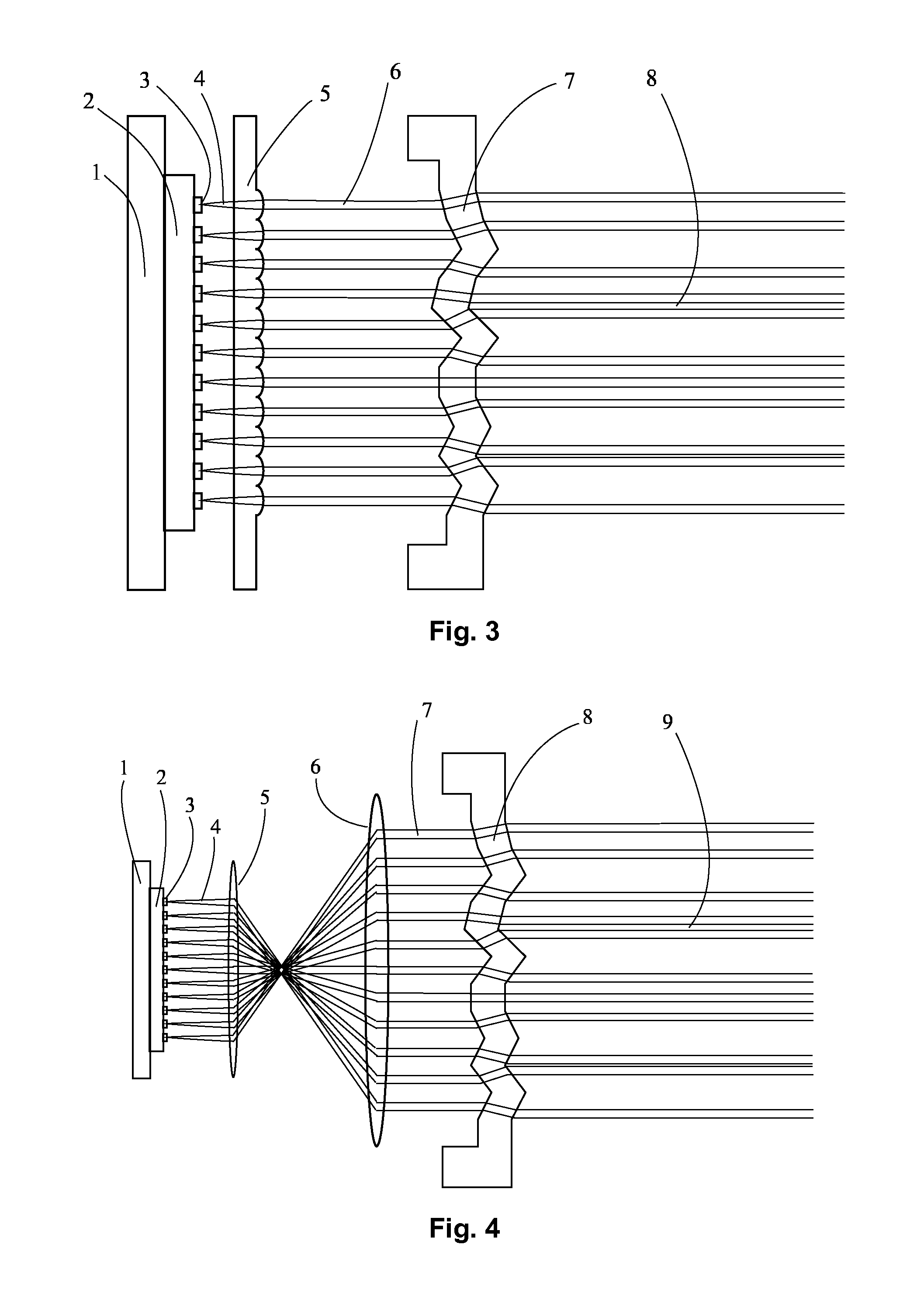
[0033]FIG. 1 shows a schematic view of the general construction of the structured light generator and its components. The different features shown in FIG. 1 are as follows: 1 heat sink and mount of the array of light sources ; 2 array of light sources ; 3 individual light source; 4 divergent single light beam; 5 beam collimation unit; 6 beams of smaller divergence; 7 structuring unit; 8 structured light beams; 9 auxiliary lens or optical system; 10 auxiliary grating unit; 11 auxiliary element to direct parts of the light field into particular regions of the field of view; 12 projection of the structured light field.

[0034]In order to realize the illuminator an array of light sources (2) is considered, which ...


PUM


Abstract

An optical system for the generation of a structured light field comprises an array of light sources and a structuring unit separate from said array of light sources, said structuring unit being refractive or reflective and transforming the output of that array of light sources into a structured light illumination by collimating the light beam of each individual light source and directing each beam into the scene under vertical and horizontal angles that can be arbitrarily chosen by refraction or reflection.

Description

TECHNICAL FIELD[0001]The present invention generally relates to the area of structured light applications, e.g. the 3D mapping by structured light triangulation e.g. in a structured light 3D scanner, and more specifically to an optical system generating a structured light field using the output of an array of light sources.BACKGROUND ART[0002]3D mapping of a scene by structured light triangulation comprises illuminating the scene with a light pattern and observing the illuminated scene with a camera whose optical axis is offset from the illumination source. If a given ray from the illumination intersects a reflective object, an image of this ray will be formed on the camera. The location of the image of this ray together with knowledge about the exact geometry of illumination-imaging setup allows the determination of the relative position of the intersection between the light ray and the object. This supposes that one knows which ray of the structured light pattern intersected the o...

Claims


Application Information

Patent Timeline
Patent Type & Authority Applications(United States)
IPC IPC(8): G02B27/09G03B15/06G01B11/25F21V5/04F21V5/00F21V5/08H01S5/42G02B27/30
CPCG02B27/0961H01S5/423G03B15/06G02B27/0977G01B11/2513F21V5/045F21V5/007F21V5/08G02B27/30
Inventor HERSCHBACH, NORBERT
Owner IEE INT ELECTRONICS & ENG SA
Why Eureka
Try Eureka