Thermoelectric-based thermal management system

a technology of thermal management system and thermal management system, which is applied in the direction of electrochemical generators, cell components, transportation and packaging, etc., can solve the problems of power electronics and other electrical devices, such as batteries, that are sensitive to overheating, cold temperatures, extreme temperatures, operating temperature limits, etc., to reduce overcooling and electrical device degradation, and achieve high current and efficiency. , the effect of reducing the incidence of overheating and overheating

Active Publication Date: 2015-12-10
GENTHERM INC
View PDF2 Cites 43 Cited by
  • Summary
  • Abstract
  • Description
  • Claims
  • Application Information

AI Technical Summary

Benefits of technology

[0005]It can be advantageous to manage the thermal conditions of power electronics and other electrical devices. Thermal management can reduce incidences of overheating, overcooling, and electrical device degradation. Certain embodiments described herein provide thermal management of devices that carry significant electric power and / or require high current and efficiency (e.g., power amplifiers, transistors, transformers, power inverters, insulated-gate bipolar transistors (IGBTs), electric motors, high power lasers and light-emitting diodes, batteries, and others). A wide range of solutions can be used to thermally manage such devices, including convective air and liquid cooling, conductive cooling, spray cooling with liquid jets, thermoelectric cooling of boards and chip cases, and other solutions. At least some embodiments disclosed herein provide at least one of the following advantages compared to existing techniques for heating or cooling electrical devices: higher power efficiency, lower or eliminated maintenance costs, greater reliability, longer service life, fewer components, fewer or eliminated moving parts, heating and cooling modes of operation, other advantages, or a combination of advantages.
[0007]The high electrical conductance of electrodes and many other types of electrical conductors also means that such conductors typically have high thermal conductivity. The high thermal conductivity can be used to solve various thermal management problems, where one can deliver desired thermal power (e.g., cooling, heating, etc.) directly to the sensitive elements of the device by heating and / or cooling the electrodes, bypassing thermally-insensitive elements of the device. Similar to using thermally conditioned blood during blood transfusions for delivering heat deep to the core of human bodies, heat pumping through the electrodes can be used to efficiently deliver desired thermal conditions deep inside an electrical device. As an example, it has been determined that electrode cooling of advanced automotive batteries is one of the most advantageous techniques for battery thermal management. For example, the electrodes can be cooled using solid, liquid, or air cooling techniques. In a sense, electrodes act as cold fingers in such a thermal management arrangement.
[0018]In some embodiments, the thermoelectric battery thermal management system comprises a blower and duct assembly attached to the printed circuit substrate and configured to push or pull air across the waste surface of the thermoelectric device. The blower and duct assembly comprises a controller in electrical communication with at least one of the battery management controller and thermoelectric management controller such that at least one of the battery management controller and thermoelectric management controller is configured to optimize system efficiency such that airflow from the blower is increased or decreased to match cooling or heating requirements of the battery cell.
[0028]In some embodiments, a blower and duct assembly is attached to the printed circuit substrate and configured to push or pull air across the waste surface of the thermoelectric device. The blower and duct assembly comprises a controller in electrical communication with at least one of the battery management controller and thermoelectric management controller such that at least one of the battery management controller and thermoelectric management controller is configured to optimize system efficiency such that airflow from the blower is increased or decreased to match cooling or heating requirements of the battery cell.
[0038]In some embodiments, the method includes attaching a blower and duct assembly to the printed circuit substrate, the blower and duct assembly configured to push or pull air across the waste surface of the thermoelectric device. The blower and duct assembly comprises a controller in electrical communication with at least one of the battery management system and thermoelectric management system such that at least one of the battery management system and thermoelectric management system is configured to optimize system efficiency such that airflow from the blower is increased or decreased to match cooling or heating requirements of the battery cell.

Problems solved by technology

Power electronics and other electrical devices, such as batteries, can be sensitive to overheating, cold temperatures, extreme temperatures, and operating temperature limits.
The performance of such devices may be diminished, sometimes severely, when the devices are operated outside of recommended temperature ranges.
In semiconductor devices, integrated circuit dies can overheat and malfunction.
In batteries, including, for example, batteries used for automotive applications in electrified vehicles, battery cells and their components can degrade when overheated or overcooled.
Such degradation can manifest itself in reduced battery storage capacity and / or reduced ability for the battery to be recharged over multiple duty cycles.
At least some such devices can have high current carrying capacity and can suffer from operation outside of a preferred temperature range.

Method used


Image

  • Thermoelectric-based thermal management system
  • Thermoelectric-based thermal management system
  • Thermoelectric-based thermal management system

Examples


Embodiment Construction

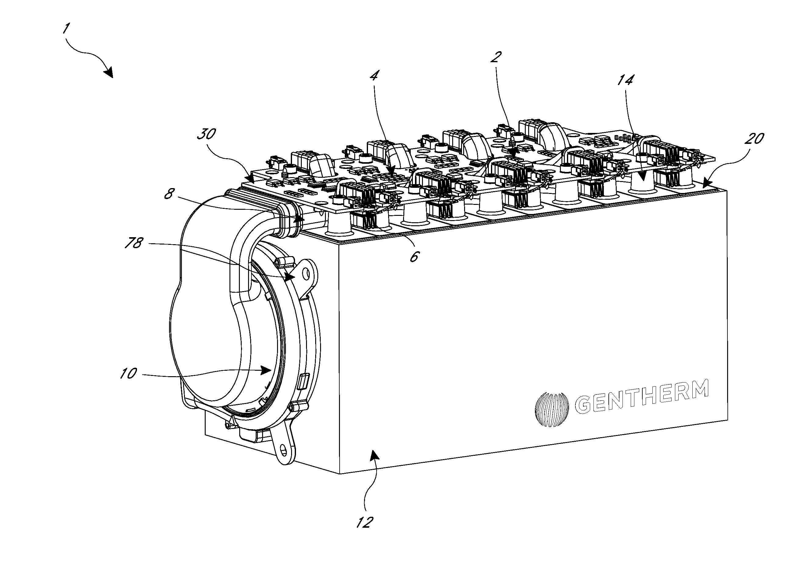
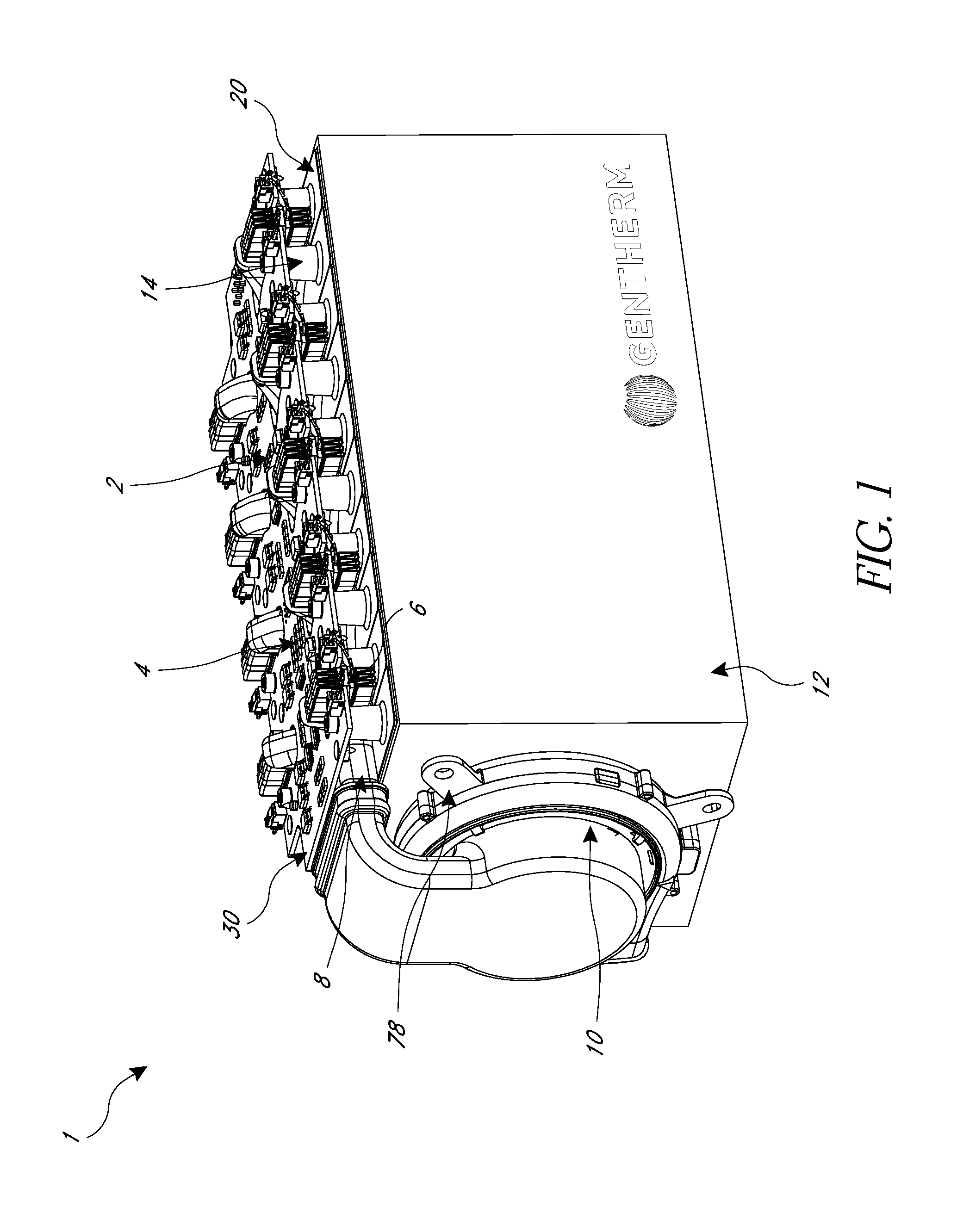
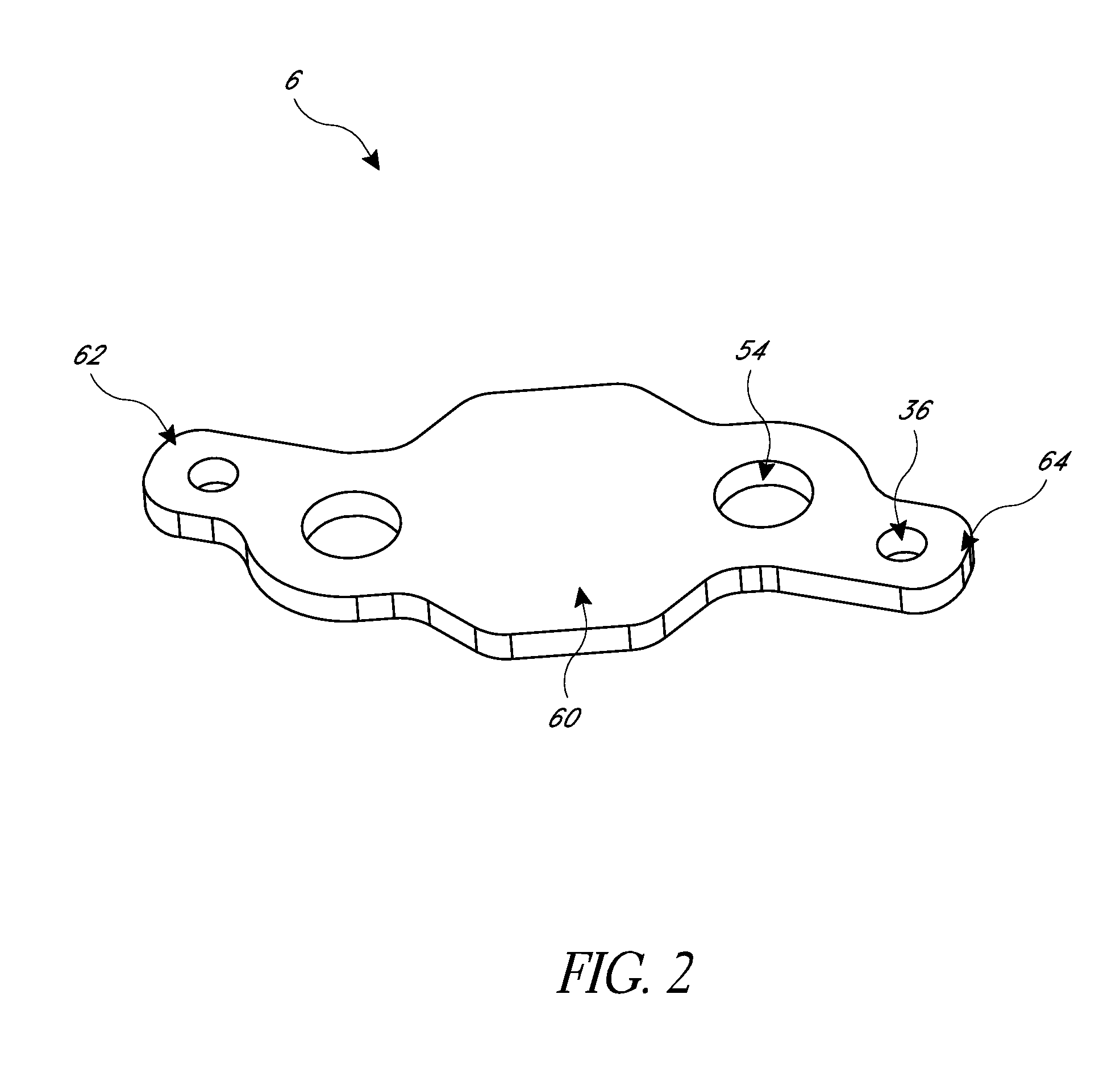
[0058]Although certain embodiments and examples are disclosed herein, the subject matter extends beyond the examples in the specifically disclosed embodiments to other alternative embodiments and / or uses, and to modifications and equivalents thereof. Thus, the scope of the claims appended hereto is not limited by any of the particular embodiments described below. For example, in any method or process disclosed herein, the acts or operations of the method or process may be performed in any suitable sequence and are not necessarily limited to any particular disclosed sequence. Various operations may be described as multiple discrete operations in turn, in a manner that may be helpful in understanding certain embodiments; however, the order of description should not be construed to imply that these operations are order dependent. Additionally, the structures, systems, and / or devices described herein may be embodied as integrated components or as separate components. For purposes of com...


PUM

PropertyMeasurementUnit
temperatureaaaaaaaaaa
thermal energyaaaaaaaaaa
thermalaaaaaaaaaa

Abstract

Disclosed embodiments include thermoelectric-based thermal management systems and methods configured to heat and / or cool an electrical device. Thermal management systems can include at least one electrical conductor in electrical and thermal communication with a temperature-sensitive region of the electrical device and at least one thermoelectric device in thermal communication with the at least one electrical conductor. Electric power can be directed to the thermoelectric device by the same electrical conductor or an external power supply, causing the thermoelectric device to provide controlled heating and / or cooling to the electrical device via the at least one electrical conductor. The thermoelectric management system can be integrated with the management system of the electrical device on a printed circuit substrate.

Description

BACKGROUND[0001]1. Field of the Disclosure[0002]This disclosure relates generally to thermoelectric (TE) cooling and heating of electrical devices.[0003]2. Description of Related Art[0004]Power electronics and other electrical devices, such as batteries, can be sensitive to overheating, cold temperatures, extreme temperatures, and operating temperature limits. The performance of such devices may be diminished, sometimes severely, when the devices are operated outside of recommended temperature ranges. In semiconductor devices, integrated circuit dies can overheat and malfunction. In batteries, including, for example, batteries used for automotive applications in electrified vehicles, battery cells and their components can degrade when overheated or overcooled. Such degradation can manifest itself in reduced battery storage capacity and / or reduced ability for the battery to be recharged over multiple duty cycles.SUMMARY[0005]It can be advantageous to manage the thermal conditions of ...

Claims


Application Information

Patent Timeline
Patent Type & Authority Applications(United States)
IPC IPC(8): H01M10/6572H02J7/00H05K3/32
CPCH01M10/6572H05K3/325Y10T29/49131Y10T29/49112H02J7/0068H01M10/613H01M10/615H01M10/655Y02E60/10H01M10/627
Inventor PIGGOTT, ALFREDKOSSAKOVSKI, DMITRIBARNHART, TODD ROBERT
Owner GENTHERM INC
Why Eureka
Try Eureka