Toric-diffractive lens

a technology of diffractive lenses and toric lenses, applied in the field of optics, can solve problems such as vision loss, vision deterioration, and reducing the perception of blue colors

Inactive Publication Date: 2015-12-17
DAVE JAGRAT NATAVAR
View PDF3 Cites 31 Cited by
  • Summary
  • Abstract
  • Description
  • Claims
  • Application Information

AI Technical Summary

Benefits of technology

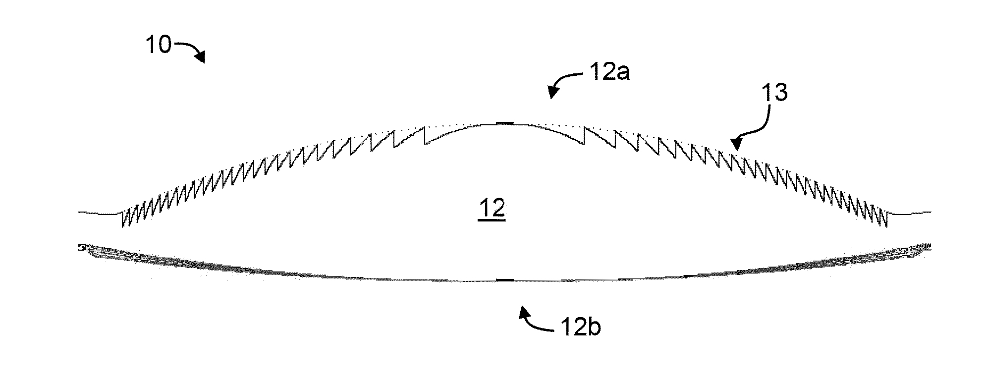
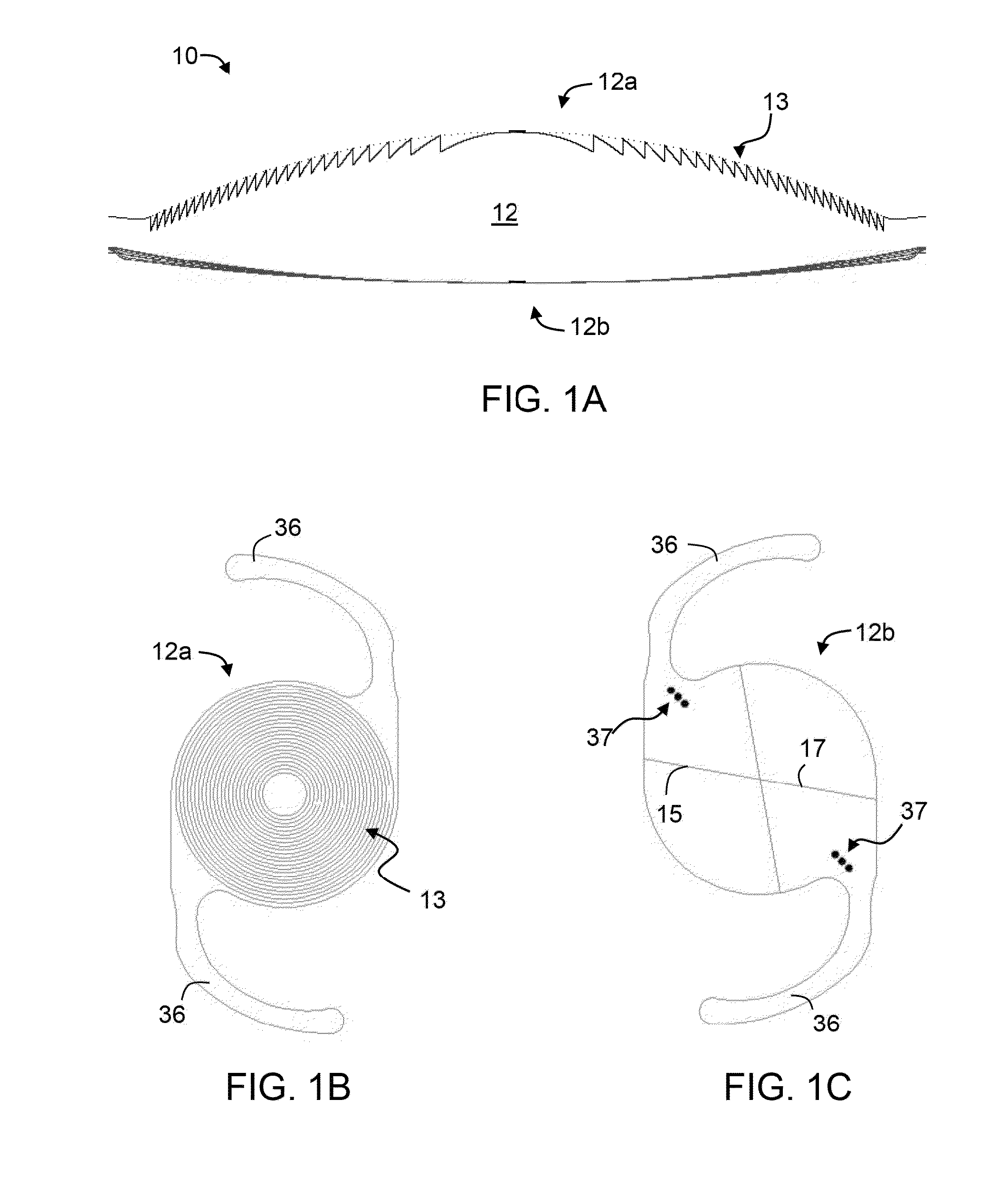
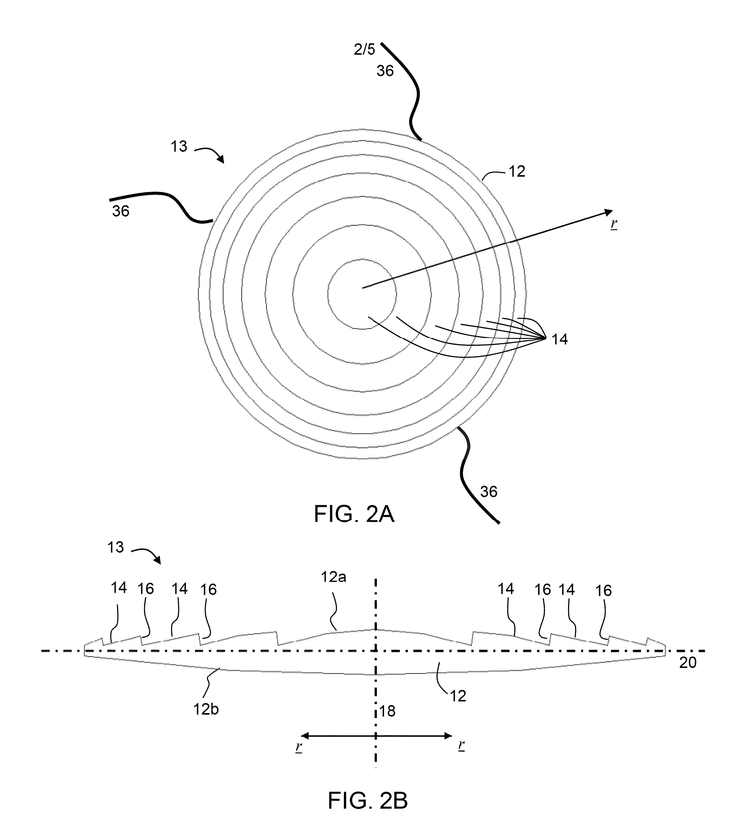
[0026]According to some embodiments of the invention the diffractive pattern comprises a plurality of concentric annular zones having surfaces separated by slanted steps having surfaces, wherein the surfaces of the concentric zones effect both diffraction and refraction of incident light, while the surfaces of the steps are substantially devoid of any diffractive or refractive power.

Problems solved by technology

When age or disease causes the lens to become less transparent, vision deteriorates because of the diminished light which can be transmitted to the retina.
Early in the development of age-related cataract the power of the lens may be increased, causing near-sightedness (myopia), and the gradual yellowing / opacification of the lens may reduce the perception of blue colors.
Cataracts typically progress slowly to cause vision loss and are potentially blinding if untreated.

Method used


Image

  • Toric-diffractive lens
  • Toric-diffractive lens
  • Toric-diffractive lens

Examples


examples

[0333]Reference is now made to the following example, which together with the above descriptions illustrates some embodiments of the invention in a non limiting fashion.

Exemplary Lens Device with 30 Diffractive Zones

[0334]A prototype lens device was designed according to various exemplary embodiments of the present invention. The lens device included 30 zones and steps.

[0335]FIG. 5A illustrates the central (innermost) zone (referred to as zone 1), and FIG. 5B illustrates the peripheral (outermost) zone (referred to as zone 30). As shown, zone 1 has a step height H=1.83 microns and slope s=84°, and zone 30 has a step height H=0.09 microns and slope s=25°. Both zones exhibit diffractive for near vision and refractive power for far vision.

[0336]The values of step height H, step slope s and step width Ws for each of the 30 steps is summarized in Table 1, below.

TABLE 1Zone Step heightStep slope Step widthNo.[μm][degrees][μm]11.83840.1921.77840.1931.71840.1841.64830.1951.57830.1961.51830....


PUM

PropertyMeasurementUnit
widthaaaaaaaaaa
heightsaaaaaaaaaa
heightsaaaaaaaaaa

Abstract

A multifocal lens device is disclosed. The device comprises, a lens body having two opposite sides, wherein a first side has an aspheric profile and a diffractive pattern formed thereon, and the second side has a toric profile and is devoid of any diffractive pattern. In some embodiments of the present invention the diffractive pattern covers at least 80% of an area of the aspheric profile.

Description

RELATED APPLICATION[0001]This application claims the benefit of priority of Indian Patent Application No. 135 / Mum / 2013 filed Jan. 15, 2013, the contents of which are incorporated herein by reference in their entirety.FIELD AND BACKGROUND OF THE INVENTION[0002]The present invention, in some embodiments thereof, relates to optics and, more particularly, but not exclusively, to intraocular and contact lenses.[0003]The human eye is a complex anatomical device, which facilitates interpretation of shapes, colors and dimensions of objects by processing the light they reflect or emit. Similarly to a camera, the eye is able to refract light and produce a focused image that can stimulate neural responses and provide the ability to see.[0004]For the purpose of providing a self-contained document, following is a description of the principle of operation of the mammalian eye, in general, and of the cornea in particular. The iris regulates the amount of light admitted to the interior of the eye, ...

Claims


Application Information

Patent Timeline
Patent Type & Authority Applications(United States)
IPC IPC(8): A61F2/16B29D11/00
CPCA61F2/1654A61F2/1618A61F2/164B29K2033/04B29D11/00019A61F2002/1681A61F2/1645A61F2002/16965A61L27/16A61L27/26G02B1/043G02B5/1876G02C7/042G02C2202/20G02B3/06G02B3/10G02C7/041G02C2202/22C08L83/08C08L83/10C08L101/14C08L33/08
Inventor ARGAL, SANJAY RAM SWAROOPHUSSAIN, MUNAVVAR TAHIR
Owner DAVE JAGRAT NATAVAR
Why Eureka
Try Eureka