Mid-infrared hyperspectral spectroscopy systems and methods therefor

a hyperspectral spectroscopy and mid-infrared technology, applied in the field of systems and methods for hyperspectral spectroscopy, can solve the problems of inability to effectively identify many chemicals, narrow bandwidth of conventional mir spectrometers, and inability to accurately identify chemicals, etc., to achieve the effect of improving system sensitivity

Active Publication Date: 2016-12-13
CALIFORNIA INST OF TECH
View PDF15 Cites 26 Cited by
  • Summary
  • Abstract
  • Description
  • Claims
  • Application Information

AI Technical Summary

Benefits of technology

[0011]The present invention provides MIR spectroscopy systems that overcome some of the costs and disadvantages of the prior art. Spectrometers in accordance with the present invention employ an MIR radiation signal to interrogate a test sample and a detector array to detect absorption in narrow spectral components of the MIR radiation as it passes through the test sample. The MIR radiation propagates through multiple stages of spectral dispersion in a hierarchical arrangement to spatially separate and direct the spectral components onto individual detector pixels. The spectral dispersion is done in hierarchical fashion with at least one stage on either side of the test sample. In some embodiments, spectral cross-talk is mitigated by using spectrally selective detector pixels, thereby improving system sensitivity. In some embodiments, spectral cross-talk is mitigated by using spectrally selective emitters, each emitting radiation having a spectral sub-range such that all of the spectral sub-ranges collectively span the MIR spectrum.
[0013]In the illustrative embodiment, each emitter is a miniature black-body radiation source that includes a diffraction grating that gives rise to narrow-spectrum radiation in its spectral sub-range, as well as encouraging the radiation from each emitter to propagate preferentially in a desired direction. In some embodiments, each emitter is optically coupled with an additional diffractive lens that focuses the radiation to give rise to an even more narrow emission pattern. In some embodiments, each emitter includes a mirror layer held above the diffractive elements to define a vertical resonant cavity between them. The inclusion of the mirror layer enables black-body radiation that is more efficiently emitted in the desired narrow spectral sub-range of each emitter.
[0014]In the illustrative embodiment, each detector in the detector array includes a group of spectrally selective pixels, each of which detects only one spectral component that includes a narrow sub-portion of the spectral range provided by its corresponding emitter. The detector pixels are cavity-enhanced detector elements defined by photonic crystals formed in a layer of weakly absorbing silicon. The surface structure of the photonic crystal gives rise to excitation of surface states that generates free-carrier pairs in the silicon, thereby enabling the generation of a macroscopically detectable photoconductive response. In addition, the design of each photonic crystal provides spectral selectivity to its respective pixel. In some embodiments, the detector pixels are conventional MIR detectors, such as non-spectrally selective bolometers or MIR-sensitive photoconductors. In some embodiments, a high electric field is applied across each pixel to foster the development of avalanche gain. In some embodiments, at least one pixel group includes a “blind” pixel that enables differential measurement of each “active” pixel referenced to the blind detector. In some embodiments, the pixels are interrogated using a pulsed scheme that enables detection of both its photoconductive and thermal response.

Problems solved by technology

Unfortunately, prior-art MIR spectroscopy systems have many drawbacks.
First, conventional MIR spectrometers suffer from narrow bandwidth.
Second, their wavelength resolution is too coarse to effectively identify many chemicals—typically due to an insufficient number of detectors.
Third, most prior-art MIR spectrometers require external sources and detectors, making them quite complex, difficult to align and keep aligned, and subject to failure due to environmental shock and vibration.
Fourth, scatter of radiation within the test sample can lead to cross-talk between detector pixels, since the output signal of each bolometer is merely a function of whatever radiation is incident upon it.
Further, prior-art spectrometers based on semiconductor detectors, which measure photoconductivity or diode current changes, have additional drawbacks.
Because of these small bandgaps, these semiconductors typically have high leakage currents that compromise the signal-to-noise performance of the detectors.
The need to operate at low temperature, however, severely limits their portability, as well as their use for biological analysis.
While conventional bolometers represent an attractive alternative to semiconductor MIR detectors in many cases, they are not without their own disadvantages.

Method used


Image

  • Mid-infrared hyperspectral spectroscopy systems and methods therefor
  • Mid-infrared hyperspectral spectroscopy systems and methods therefor
  • Mid-infrared hyperspectral spectroscopy systems and methods therefor

Examples


Embodiment Construction

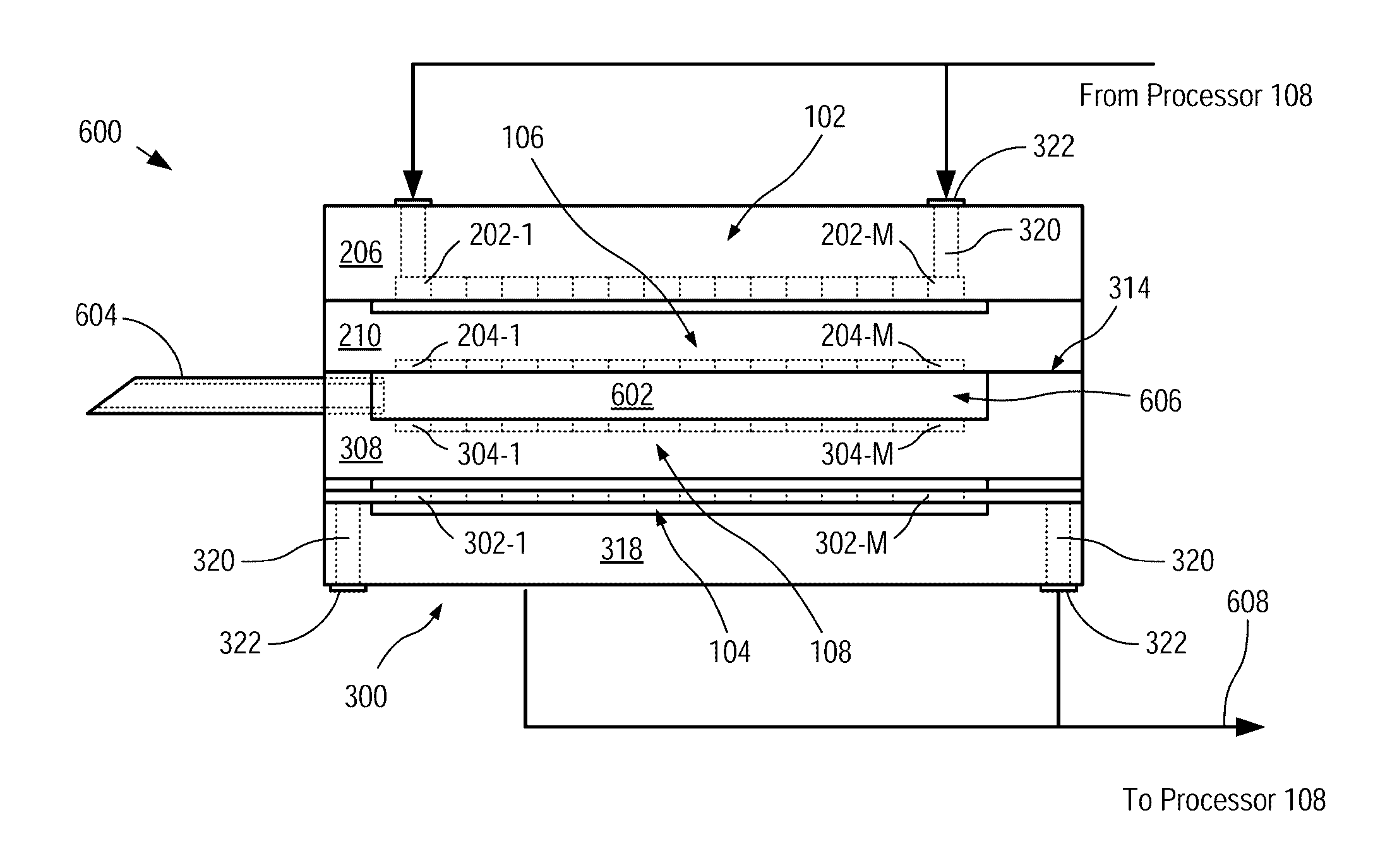
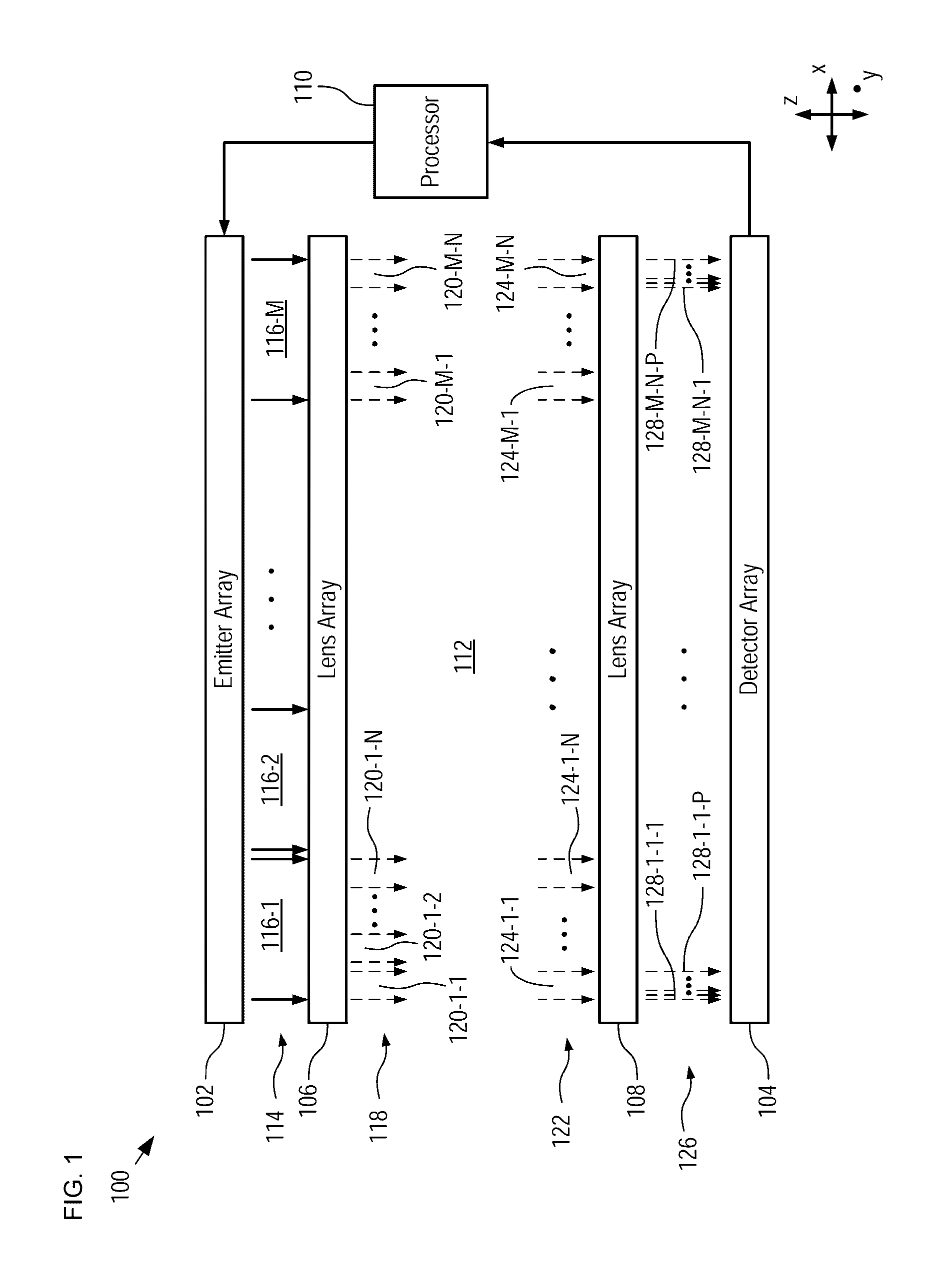
[0036]In is an aspect of the present invention that significant advantages over MIR spectroscopy systems of the prior art are derived by employing a hierarchical wavelength-segmentation approach. In embodiments of the present invention, the MIR spectrum is segmented into a plurality of spectral sub-ranges by employing an array of emitters, each of which emits radiation in only one of the spectral sub-ranges. The radiation from each emitter is further segmented by directing it only onto a detector comprising a plurality of detector pixels, each of which selectively detects radiation in a sub-portion of the spectral sub-range of that detector. Further, each detector is optically coupled with its respective emitter via a filter element that directs each sub-portion to its corresponding detector pixel. The use of multiple emitters in an array, along with diffractive optical filters that match those sources with spectrally selective detector elements, the entire MIR spectrum can be detec...


PUM

PropertyMeasurementUnit
wavelengthsaaaaaaaaaa
wavelength selectivityaaaaaaaaaa

Abstract

MIR spectroscopy systems comprising hierarchical spectral dispersion that enables fine spectral resolution and high sensitivity spectroscopy are disclosed. Hierarchical spectral dispersion is derived by employing at least two diffractive lens arrays, located on either side of a test sample, each receiving input radiation having an input spectral range and distributing the input radiation into a plurality of output signals, each having a fraction of the spectral range of the input radiation. As a result, the signal multiplication factor of the two arrays is multiplied in a manner that mitigates the propagation of wavelength harmonics through the system. In some embodiments, an emitter array comprising a plurality of spectrally selective emitters provides the input MIR radiation to a spectroscopy system. In some embodiments, spectrally selective detectors are used to detect narrow spectral components in the radiation after they have passed through the test sample.

Description

CROSS REFERENCE TO RELATED APPLICATIONS[0001]This case claims priority of U.S. Provisional Patent Application Ser. No. 62 / 130,357, filed Mar. 9, 2015, U.S. Provisional Patent Application Ser. No. 62 / 235,687, filed Oct. 1, 2015, and U.S. Provisional Patent Application Ser. No. 62 / 264,752, filed Dec. 8, 2015, each of which is incorporated by reference. If there are any contradictions or inconsistencies in language between this application and one or more of the cases that have been incorporated by reference that might affect the interpretation of the claims in this case, the claims in this case should be interpreted to be consistent with the language in this case.FIELD OF THE INVENTION[0002]The present invention relates to systems and methods for hyperspectral spectroscopy and, more particularly, to hyperspectral spectroscopy in the mid-infrared wavelength range.BACKGROUND OF THE INVENTION[0003]Infrared spectroscopy is a technique for analyzing the chemical makeup of a sample and is w...

Claims


Application Information

Patent Timeline
Patent Type & Authority Patents(United States)
IPC IPC(8): G01N21/35G01J3/42G01N21/3577G01J3/28
CPCG01N21/3577G01J3/2803G01J3/42G01J3/0256G01J3/18G01J3/36G01J2003/1213G01J3/0208G01N21/3563G01N2021/3148G01N2201/0245G01N2201/0638G01J3/108G01N21/35G01N21/03
Inventor SCHERER, AXELHARTLEY, FRANK T.
Owner CALIFORNIA INST OF TECH
Why Eureka
Try Eureka