
Propulsion and steering device installed below sea level of outside of right and left shipwall in a ship

a technology of propulsion and steering device, which is applied in the direction of marine propulsion, special-purpose vessels, vessel construction, etc., can solve the problems of reduced propulsion efficiency, affecting the sailing of the hull, and affecting so as to reduce the discharge amount of carbon dioxide, increase the maneuverability of the warship and the ship, and reduce the effect of vibration and nois

Inactive Publication Date: 2015-12-17
SONG GYUNG JIN +7
View PDF0 Cites 6 Cited by
  • Summary
  • Abstract
  • Description
  • Claims
  • Application Information

AI Technical Summary

Benefits of technology

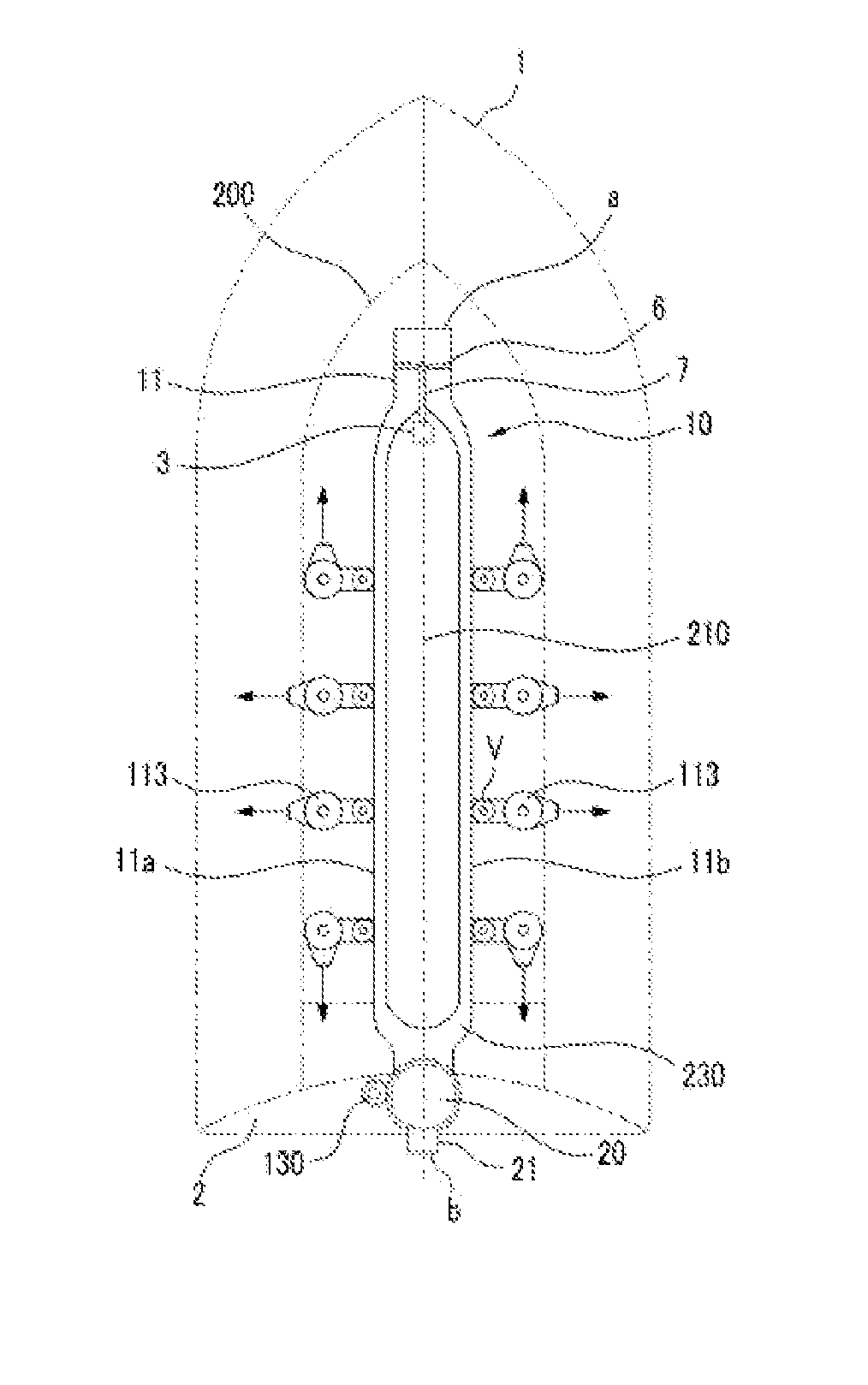
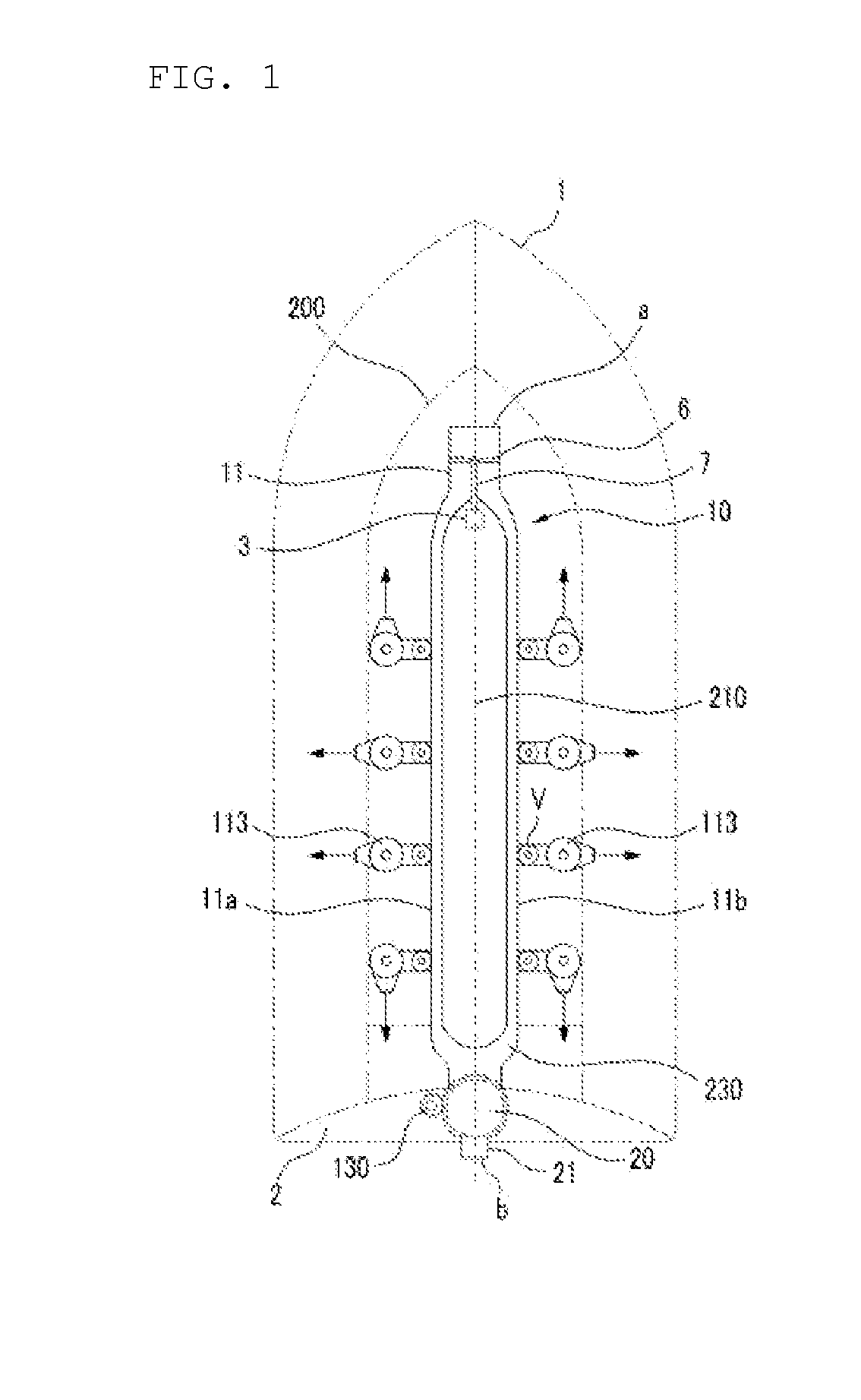
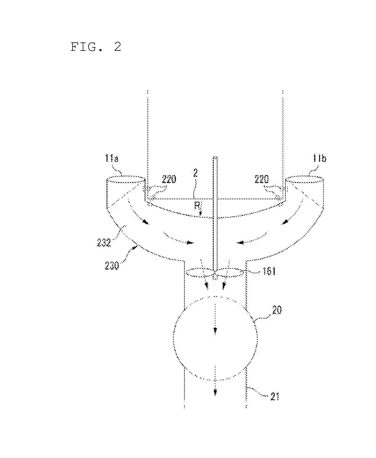
The present invention provides a propulsion and steering device for a ship that can increase convenience and stability when switching to an environment-friendly warship or ship, or when coming alongside a pier. It reduces carbon dioxide emissions and increases maneuverability while also being cost-effective and easy to repair. The device achieves low noise, small vibration, and low fuel consumption by sucking sea water in the bow and introducing it towards the screw propeller through the movement of the ship. It also minimizes friction with the water due to the diameter of the main pipe of the manifold being greater than the diameter of the water intake of the bow.

Problems solved by technology

However, vibration and noise may occur due to cavitation caused by the higher speed of the hull.
When the typical propeller which is a general propulsion device of the hull has a high load, it is highly likely to cause the cavitation, so that a reduction in propulsion efficiency, and vibration and noise of the hull may be caused.
Furthermore, the sailing of the hull may be encumbered due to the damage caused by bending and erosion of the propeller blade.
In addition, since the maintenance of the hull is performed in a stop state in order to perform the maintenance of the propulsion device, work efficiency in the maintenance may be degraded.
In addition, the propeller propulsion device has a limit on a speed of about 35 knots.
Accordingly, since the cavitation occurs in a warship and a ship such as a high-speed ship, a fire boat, a rescue ship, a look-up ship or a patrol craft that requires high speed and maneuverability in an emergency situation, it may be difficult for the hull to exhibit its own function.
Further, when an object that is likely to collide with the hull approaches in a moving direction, it may be difficult for the existing propeller hull to quickly turn or suddenly stop.
However, this ship propulsion device poses a problem in that since a screw propeller is supported within a guide pipe by a bearing, a load acting on the guide pipe is increased, and thus structural stability of the guide pipe is largely degraded.
Accordingly, a connection part between the guide pipe and the steering pipe may be easily deformed or damaged to cause a structural defect, and a fatigue load may be accumulated on the guide pipe for a long time to largely worsen structural stability.
However, in the ship propulsion device having such a configuration, since the rotation of the guide pipe is restricted, the screw propeller needs to be reversely rotated in order to move the ship backward.
For this reason, a separate gear changing unit is needed, and thus a configuration of the ship may become complicated.
As a result, it may be difficult to perform the maintenance of the ship, and it may be difficult to economically manufacture the ship.

Method used


Image

  • Propulsion and steering device installed below sea level of outside of right and left shipwall in a ship
  • Propulsion and steering device installed below sea level of outside of right and left shipwall in a ship
  • Propulsion and steering device installed below sea level of outside of right and left shipwall in a ship

Examples


Embodiment Construction

[0036]Hereinafter, the present invention will be described in more detail with reference to the drawings.

[0037]The terms “module” and “unit” used for components in the following description are merely used to easily draft the present specification, and the terms “module” and “unit” may be interchangeably used.

[0038]Further, embodiments of the present invention will be described in detail with reference to the accompanying drawings and the description taken in conjunction with the accompanying drawings, but the present invention is not limited by the embodiments.

[0039]Although the terms used in the present specification are selected from widely used terms in consideration of their functions in the present invention, the terms used herein may be variable depending on intention of a person skilled in the art, practices or appearance of a new technology. In addition, in special cases, the terms mentioned herein may be selected by the applicant at his or her discretion, the detailed mean...


PUM


Abstract

There is provided a propulsion and steering device installed below a sea level of outsides of right and left ship walls in a ship. The device includes a manifold that is installed at a bottom of a hull in a longitudinal direction, and drains water introduced into a bow toward a stern; a propulsion unit that has a lower end rotatably connected to an end of the manifold close to the stern within a 360-degree range, and is provided to laterally discharge water; and a steering unit that is rotatably coupled to an end of the propulsion unit close to the stern, and rotates the propulsion unit in an arbitrary direction by a rotational force exerted from an outside.

Description

CROSS-REFERENCE TO RELATED APPLICATIONS[0001]This application claims the priority of Korean Patent[0002]Application No. 10-2014-0071634 filed on Jun. 12, 2014, in the Korean Intellectual Property Office, the disclosure of which is incorporated herein by reference.BACKGROUND OF THE INVENTION[0003]1. Field of the Invention[0004]The present invention relates to a propulsion and steering device installed below a water level of outsides of right and left ship walls in a ship with which it is possible to allow a warship or all ships to move forward and to change its direction by rapidly discharging sea water introduced through a bow in the warship or all ships. More particularly, the present invention relates to a propulsion and steering device installed below a water level of outsides of right and left ship walls in a ship with which it is possible to increase convenience and stability when a ship is switched to an environment-friendly warship or ship or when the ship comes alongside the...

Claims


Application Information

Patent Timeline
Patent Type & Authority Applications(United States)
IPC IPC(8): B63H11/08B63H11/10
CPCB63H11/08B63H2011/008B63H11/10B63H25/46Y02T70/50
Inventor SONG, GYUNG JINSONG, YOUNG SICKSONG, WON GISONG, WON CHANSONG, JUNG SIKSONG, IN JUNGCHAE, JE WANCHAE, HEON
Owner SONG GYUNG JIN
Learn More