
Destacking device and method for destacking metal sheets

a destacking device and metal sheet technology, applied in metal-working feeding devices, stacking articles, de-stacking articles, etc., can solve the problems of long airflow path, long destacking path, and inability to destack, etc., to facilitate the destacking of thin sheets, high rate, and easy dispensing of separation air

Active Publication Date: 2015-12-17
SOUDRONIC
View PDF14 Cites 5 Cited by
  • Summary
  • Abstract
  • Description
  • Claims
  • Application Information

AI Technical Summary

Benefits of technology

The patent describes a new device for destacking thin sheets made of metal. The device uses magnetic holding means to securely hold the sheets in place without damaging them. The device also includes a suction element that helps to detach the sheets from the stack, allowing air to flow between them. This means that even thin sheets can be easily removed from the stack without causing any damage. Overall, the device improves efficiency and prevents damage during the destacking process.

Problems solved by technology

Otherwise multiple sheets are destacked simultaneously, which results in undesirable disruptions and in production downtime and material losses.
It has been shown that destacking becomes problematic in the above-described conventional manner with thin sheets (which is considered to include metal sheets having a thickness of less than 0.14 mm), and in particular with square sheet formats, in which the path for air to flow in from all sides is long.
The separating air is poorly suited for thin sheets since these metal sheets are not sufficiently stable and may fall downward out of the stacking magazine as a result of the use of the separating air.

Method used


Image

  • Destacking device and method for destacking metal sheets
  • Destacking device and method for destacking metal sheets
  • Destacking device and method for destacking metal sheets

Examples


Embodiment Construction

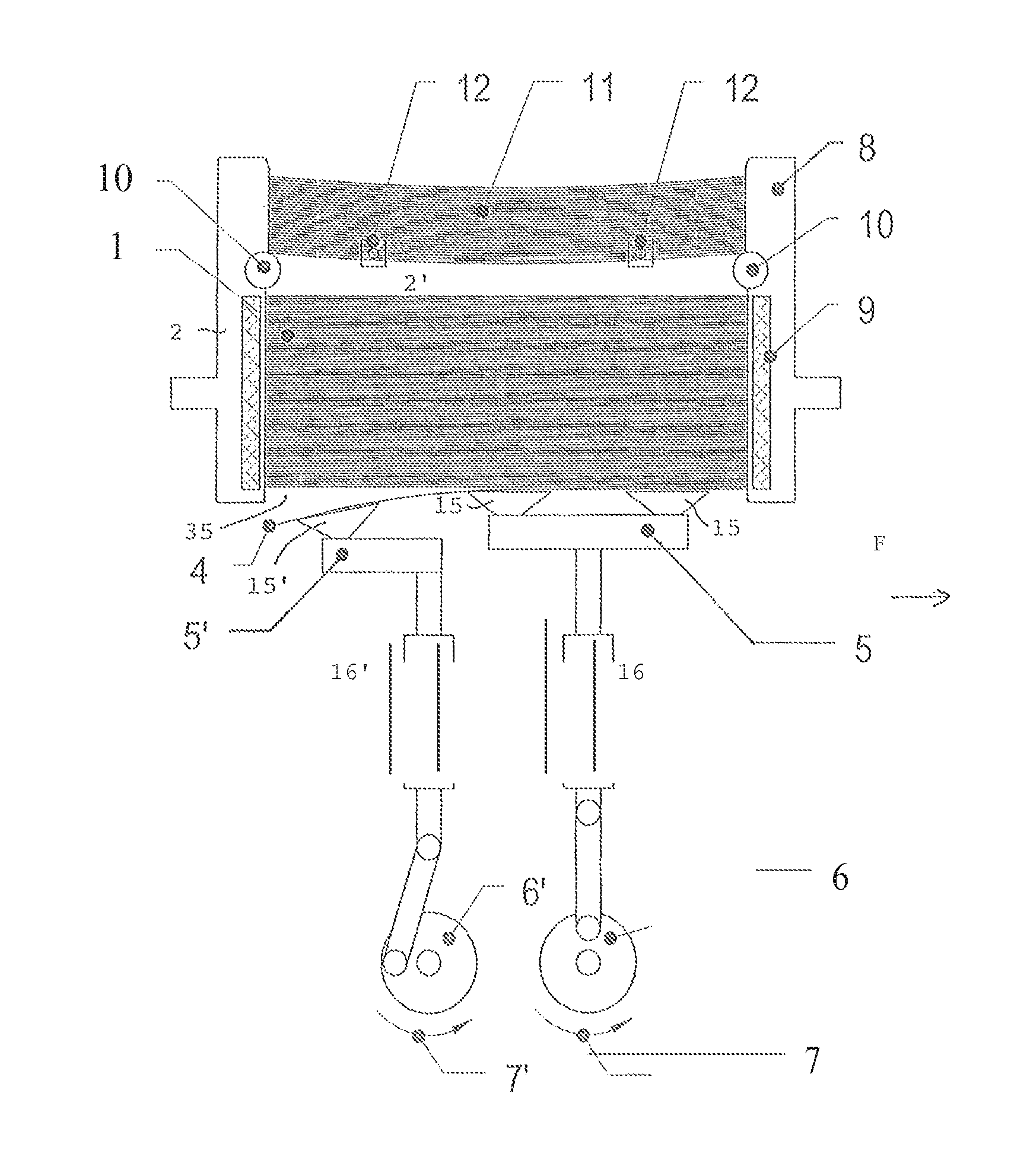
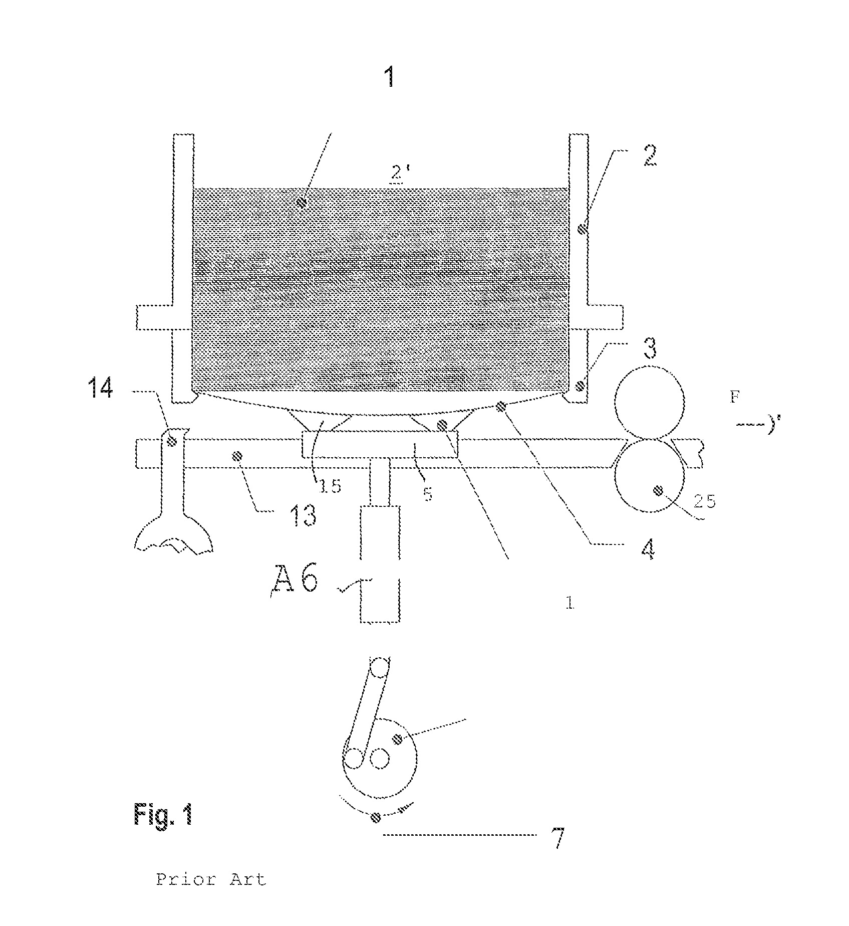
[0024]FIG. 1 shows a schematic view of a vertical section through a destacking device according to the prior art. The stack 1 composed of the individual metal sheets situated on top of each other is located in a stacking magazine 2, the bottom side of which is open and the boundaries of which form a cavity or a receptacle 2′ for the sheet metal stack 1. At the lower end of the receptacle 2′, the sheet metal stack 1 is seated against lateral support rails 3 on the lower opening of the stacking magazine. Support rails or so-called support detents can likewise be provided on the other two sides of the receptacle, which is known to the person skilled in the art. The lowest metal sheet 4 is contacted by a drivably upward and downward moving suction head 5 having multiple suction cups in the uppermost position of the suction head and is attracted to the suction head using negative pressure. The suction head is connected to a negative pressure source for this purpose, and the negative pres...


PUM

PropertyMeasurementUnit
Thicknessaaaaaaaaaa
Angleaaaaaaaaaa

Abstract

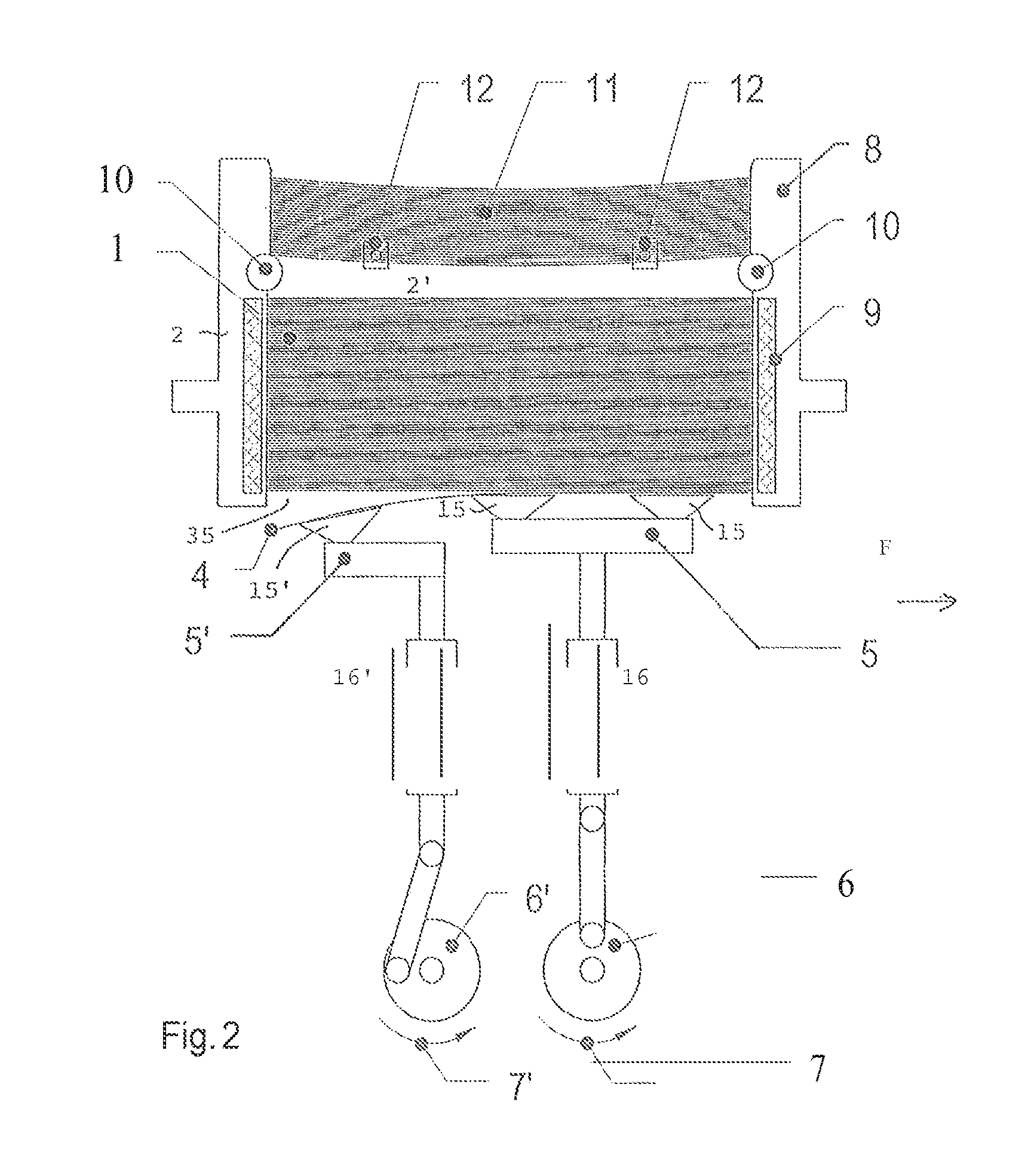
In a destacking device comprising a stacking magazine (2), the respective lowest sheet of a stack (1) of metal sheets is destacked by way of a suction element (5, 15). This element can be moved upward and downward by way of a drive (6). At the end of the upward movement, the respective lowest metal sheet (4) of the stack (1) is gripped by suction power and pulled from the stack. A second suction element (5′, 15′) is provided, which can be moved upward and downward by way of a drive (6′) and by way of which the lowest sheet (4) of the stack (1) can be gripped at the end of the upward movement. The second suction element is driven so as to be leading with respect to the first suction element, so that the respective lowest sheet (4) of the stack (1) can first be pulled from the stack by the second suction element (5′), and subsequently by the first suction element (5). In this way, it becomes possible to destack thin sheets having a thickness of only 0.12 mm and a square shape without disruption. The stack is held magnetically in the stacking magazine, which facilitates destacking.

Description

CROSS REFERENCES TO RELATED APPLICATIONS[0001]This application claims the priority of Swiss patent application No. 2836 / 12, filed Dec. 17, 2012, the disclosure of which is incorporated herein by reference in its entirety. The application is also a nationalization of PCT Application Number PCT / CH2013 / 000205 filed Nov. 29, 2013 which is incorporated herein by reference in its entirety.FIELD OF THE INVENTION[0002]The invention relates to a destacking device, comprising a stacking magazine that is open on the bottom side and a pull-off device that is disposed beneath the stacking magazine and has a drivably upward and downward movable suction element, which, in the reversal position thereof from the upward movement to the downward movement, is positioned within the lower opening of the stacking magazine, for gripping the respective lowest sheet by way of negative pressure and pulling the gripped sheet from the stack. The invention further relates to a destacking device according to clai...

Claims


Application Information

Patent Timeline
IPC IPC(8): B65G59/06B65G57/03
CPCB65G59/062B65G57/03B65G2814/0308B65G2814/0305B65G2201/022B21D43/22B21D51/26B23K11/087B65H1/06B65H3/085B65H3/0883B65H3/48B65H2403/532B65H2701/173B21D43/24B65H1/30B65H3/34
Inventor TAIANA, PETER
Owner SOUDRONIC
Learn More