Fluorescent lamp testing device

a technology of fluorescent lamps and testing devices, which is applied in the direction of measurement devices, discharge tube testing, instruments, etc., can solve the problems of migraine headaches, certain fluorescent lamps, trigger migraines, etc., and achieve the effect of preventing damag

Active Publication Date: 2015-12-17
JOHN FLUKE MFG CO INC
View PDF9 Cites 2 Cited by
  • Summary
  • Abstract
  • Description
  • Claims
  • Application Information

AI Technical Summary

Benefits of technology

[0007]The embodiments disclosed herein overcome individual problems of the prior art test equipment and discriminators by providing a comprehensive device that not only performs all electrical tests for fluorescent tubes, but also discriminates between fluorescent lighting fixtures having magnetic ballasts and those having electronic ballasts. The embodiments provide in a single device all of the tests that would be required for fluorescent lighting fixtures regardless of the purpose of the tests, i.e., electrical testing or legal compliance. The embodiments also provide protection for the antenna horn to prevent damage during ordinary use.
[0008]An embodiment of the fluorescent lamp testing device has a rectangular body with two relatively short ends opposite each other. A collapsible antenna is disposed at one short end. The horn is centered on the short end and collapses to or below the walls at the short end to protect the antenna from damage. At the other short end, there is a pair of pin terminals for testing the continuity of the filaments in a fluorescent tube. The rectangular body has an elongated surface disposed between the opposing short ends of the body. Below the surface there is operational circuitry for carrying out the electrical testing and ballast discrimination. Control buttons on the control panel are coupled to the operational circuitry and enable the user to perform ballast discrimination and other electrical tests. The ballast discrimination control button has two indicators closely associated with it that emit a recognizable signal to discriminate between magnetic and electronic ballasts. A third indicator, a large light-emitting diode (LED), is disposed proximate the short end of the device near the pin terminals. The LED is a two-color device and provides adequate information on the gas integrity, ballast operation, and noncontact voltage.

Problems solved by technology

However, fluorescent lamps have certain disadvantages.
Other studies indicate that fluorescent lamps with low frequency magnetic ballasts generate flicker, which may induce migraine headaches.
Such lamps may also establish a beat frequency with computer displays that can also trigger migraines.
Because of the foregoing potential and actual health hazards of fluorescent lamps with magnetic ballasts, regulatory entities now limit fluorescent fixtures with magnetic ballasts to outdoor use only.
Fluorescent lighting fixtures are more complex than incandescent lighting fixtures and there are a number of reasons why a fluorescent light bulb may fail.
In some cases, the gas inside the fluorescent tube leaks out and the fluorescent lamp cannot conduct current to provide light.
It is also possible that the filaments used to excite the gas within the fluorescent tube may be burned out or otherwise disabled.
Other problems include broken portions of the lighting fixture such as the so-called “tombstone” connectors that receive the pins of an elongated fluorescent bulb.
In addition, every fluorescent bulb has some kind of ballast, and the ballast may have failed.
Another source of breakdown is an open circuit in the line voltage leading to the ballast.
However, conventional test equipment cannot discriminate between magnetic and electronic ballasts.
However, such discriminator devices do not provide any other electrical testing for the fluorescent lamp and lighting fixture.

Method used


Image

  • Fluorescent lamp testing device
  • Fluorescent lamp testing device
  • Fluorescent lamp testing device

Examples


Embodiment Construction

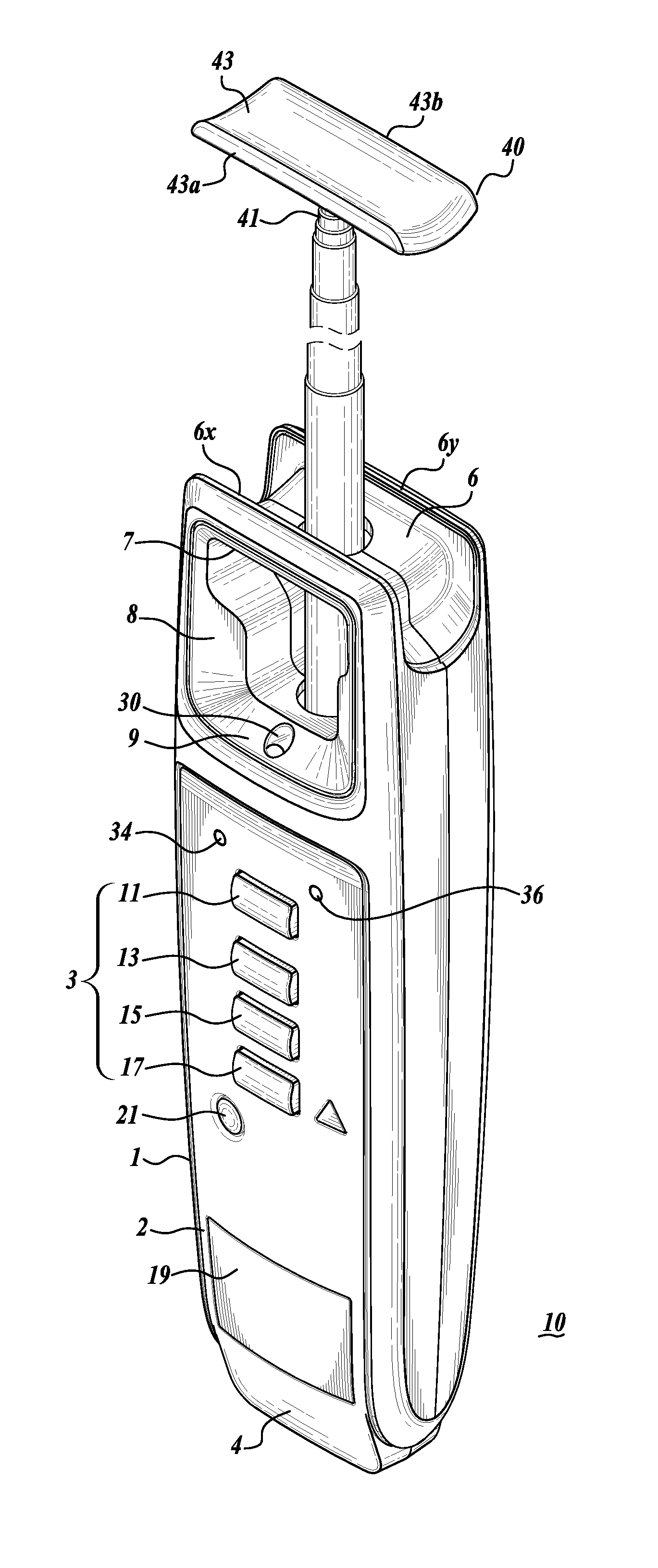
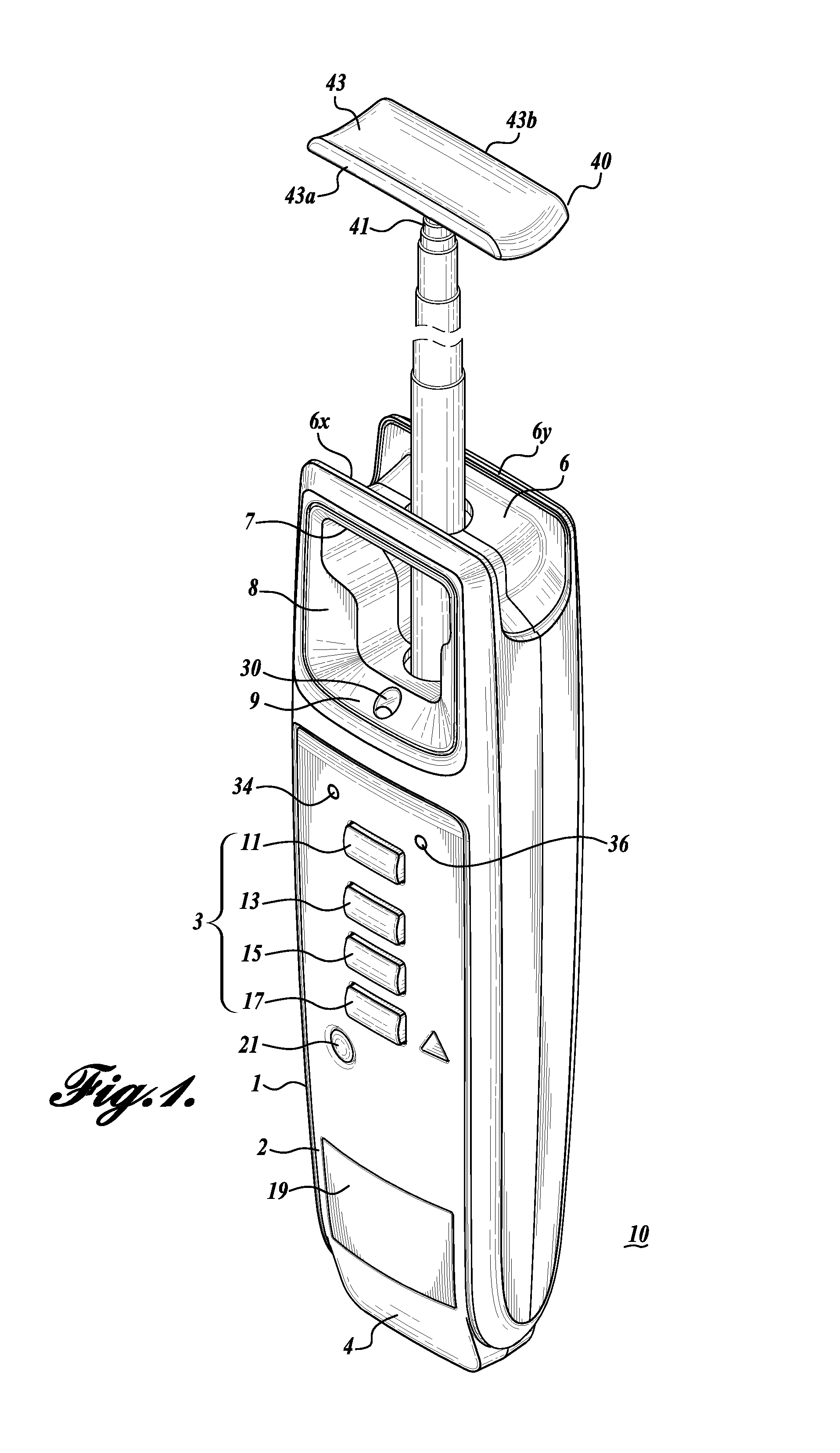
[0019]Turning to FIG. 1, there is shown a device 10 for testing fluorescent lamps and lighting fixtures. The device has an elongated rectangular body 1 with two relatively short ends 4, 6 opposite each other. The rectangular body has an elongated surface 2 disposed between the opposing short ends 4, 6 of the body 1. The elongated surface 2 includes a control panel 3. The control panel 3 includes a number of operator input buttons: button 21 turns the device 10 on or off, button 11 initiates a test for discriminating the ballast type, button 13 initiates a test for gas integrity, button 15 initiates a test to determine the operability of the ballast in the fluorescent lighting fixture, and button 17 initiates a non-contact voltage test to determine whether or not AC line voltage is available to the lighting fixture. Indicator lights 34, 36 indicate whether a ballast under test a magnetic or electronic ballast, respectively. Pin receiver terminals 52, 53 are on the short end 4 of the ...


PUM


Abstract

A fluorescent lamp testing device 10 has a microcontroller 100 that controls tests for ballast discrimination as well as gas integrity, ballast operation, filament continuity and line voltage. The ballast discrimination test is performed by the microcontroller 100 in combination with a photodiode 30 and high / low pass filter 32. Gas integrity is tested with pulse width modulation and a high-voltage, step-up transformer (PWM / T) circuit 42 and an antenna 40. A built in continuity tester has input pins 52, 54 to test the continuity of the filaments in the fluorescent lamp 12. The antenna 40 and a voltage-divider / voltage-sensor connected to the secondary coil in the transformer test for ballast operation. A PCB conductive loop 18, rectifier 20 and op amp 22 test for line voltage.

Description

BACKGROUND[0001]Fluorescent lamps are ubiquitous in industrial, commercial, and residential establishments. Studies indicate that fluorescent lamps more efficiently generate light than incandescent lamps. Recent changes in federal laws that mandate improved efficiency of all lamps will likely result in higher production and use of fluorescent lamps. However, fluorescent lamps have certain disadvantages. Other studies indicate that fluorescent lamps with low frequency magnetic ballasts generate flicker, which may induce migraine headaches. Such lamps may also establish a beat frequency with computer displays that can also trigger migraines. Conventional magnetic ballasts may be insulated with PCB materials that are poisonous to humans. Because of the foregoing potential and actual health hazards of fluorescent lamps with magnetic ballasts, regulatory entities now limit fluorescent fixtures with magnetic ballasts to outdoor use only. It is either mandated or common practice to replace...

Claims


Application Information

Patent Timeline
Patent Type & Authority Applications(United States)
IPC IPC(8): G01R31/24
CPCG01R31/245G01R31/44
Inventor MARZYNSKI, MATTHEW B.RODRIGUEZ, RICARDO
Owner JOHN FLUKE MFG CO INC
Why Eureka
Try Eureka