Wide field imaging using physically small detectors

a detector and wide field technology, applied in the field of imaging techniques, can solve the problems of large detectors, large detector arrays, and high cost, and achieve the effects of improving resolution, reducing cost, and improving accuracy

Inactive Publication Date: 2015-12-17
YEDA RES & DEV CO LTD
View PDF1 Cites 2 Cited by
  • Summary
  • Abstract
  • Description
  • Claims
  • Application Information

AI Technical Summary

Benefits of technology

[0003]There is a need in the art for a novel technique enabling to use a detector of limited physical size for imaging (photographing) a large field of view (angular extent of target sky or remote background) with high spatial resolution (small pixel size) and minimal noise.
[0004]The present invention solves the above problem of imaging a relatively wide field of regard on a relatively small light sensitive surface with high spatial resolution by providing a novel optical system enabling “segmentation” of the wide field of regard into multiple narrower fields of view by means of arrangement of collimators. The segmenting optical system of the invention may be used in various applications including, but not limited to, a so-called “multiplexing imaging” method and system utilizing concurrent and / or sequential direction of light portions from numerous locations in the image plane of the optical system (which is the focal plane in a telescope) onto a single, e.g. small-size, detector, which records the so-obtained light, e.g. combined light being a superposition of image parts from many locations in the field of regard (sky locations), in a single digital image file. This technique may be followed by analysis using an appropriate image processing algorithm that recovers from the combined image the individual contribution of each location (sky location), enabling reconstruction of the sources within a wide field of regard (large sky area).

Problems solved by technology

Covering a wide field of regard at high spatial resolution requires a detector with a large physical area and many pixels, resulting in an expensive and complex system.
The conventional imaging systems used in astronomy thus either utilize complex and expensive arrays of detectors, or detectors with relatively large pixels, at the expense of resolution.

Method used


Image

  • Wide field imaging using physically small detectors
  • Wide field imaging using physically small detectors
  • Wide field imaging using physically small detectors

Examples


Embodiment Construction

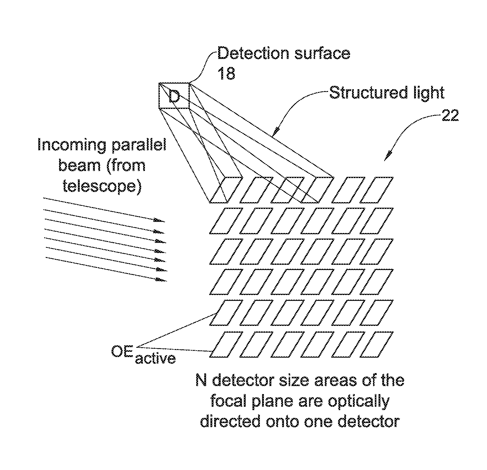
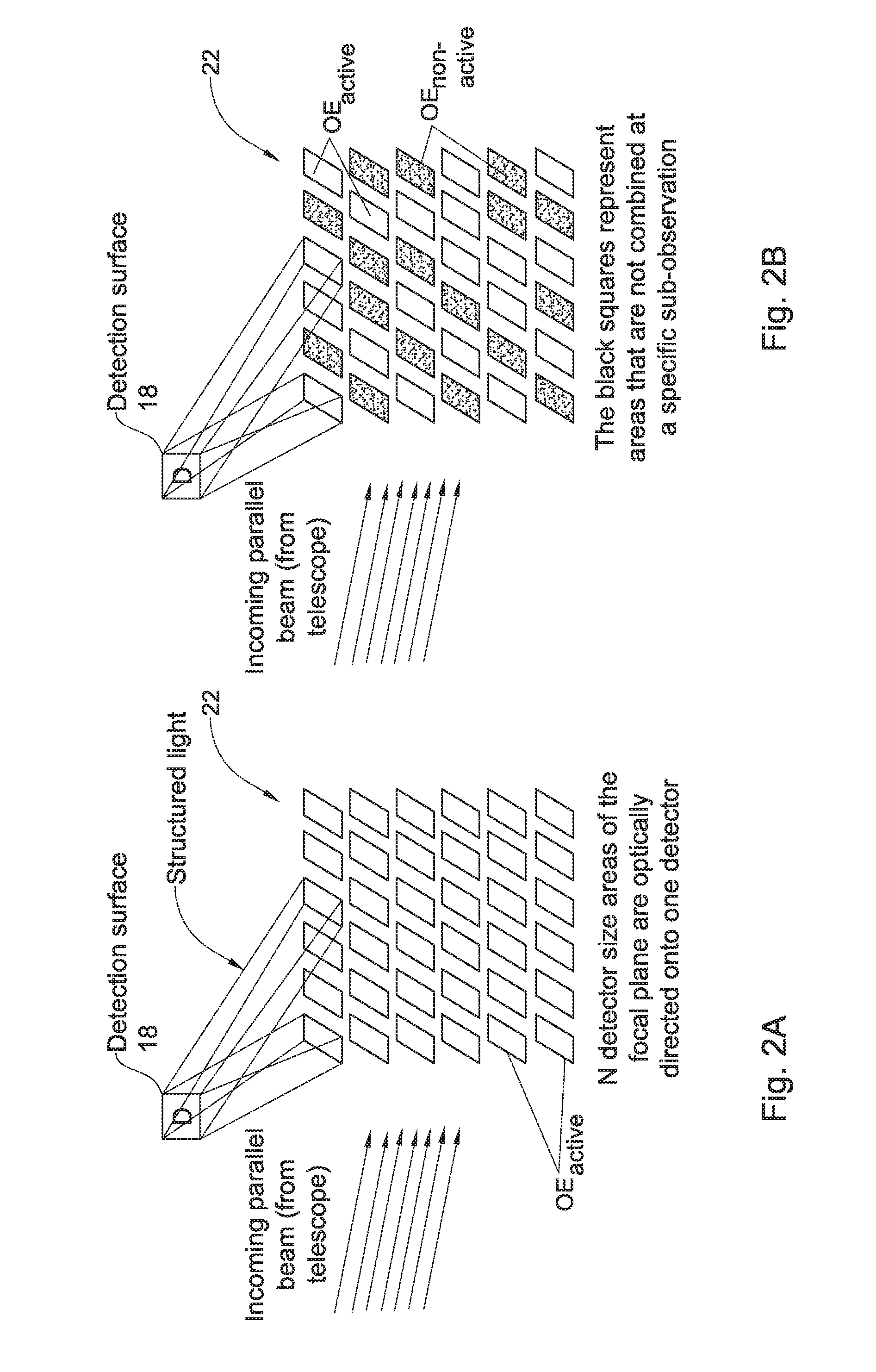
[0035]The present invention provides a novel imaging technique suitable for imaging a wide field of regard on a relatively small size detector (i.e. its light sensitive surface). This significantly simplifies the configuration of an imaging system and reduces its costs.

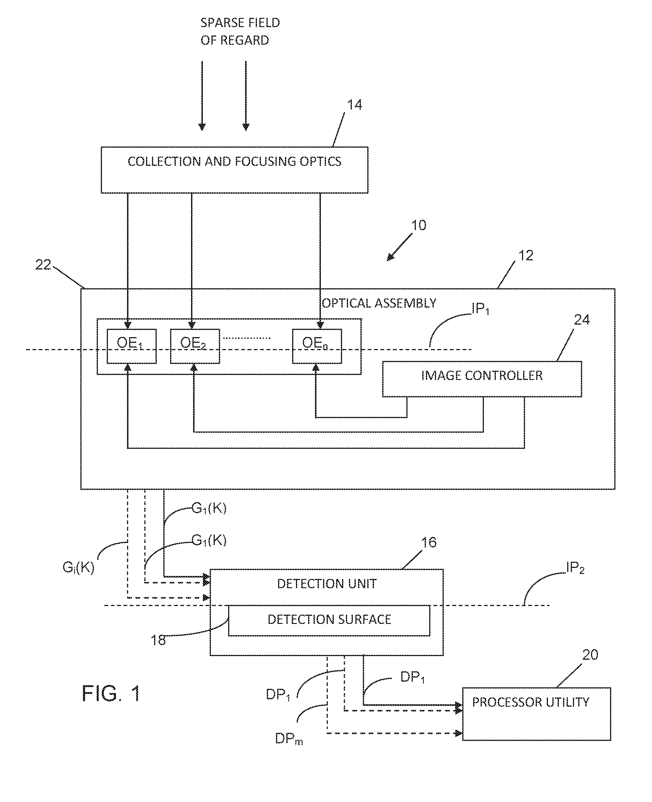
[0036]Reference is made to FIG. 1 showing, by way of a block diagram, an imaging system 10 of the present invention. The system 10 can generally be used with any imaging optics, namely collecting and focusing optics 14, as well as for imaging any object, real or imaginary, provided the F / # is known and stable. The light collecting and focusing optics 14 defines an image plane. The system 10 includes an optical assembly 12 which is to be accommodated such that its principle plane is located in an effective object plane IP1 at a predetermined relation / distance with respect to the image plane defined by the light collecting and focusing optics 14, e.g. in the image plane itself (i.e. zero distance therefrom) or at a dist...


PUM


Abstract

An imaging method and system are provided, being particularly useful for imaging a relatively wide field of regard on a relatively small detection surface with high spatial resolution. The method comprises: creating a segmented image of a field of regard in an effective object plane, said image being formed by an array of N image parts of the field of regard; and projecting a selected number M≧1 of patterns of structured light onto a detection surface, which is located in a plane conjugate to the effective object plane and has geometry and size substantially of the image part, each of the M patterns being formed by selected K light components of said N image parts concurrently projected onto the entire detection surface forming a superposition of the K image parts, thereby enabling reconstruction of the image of the field of regard from detected number M of patterns of the structured light.

Description

TECHNOLOGICAL FIELD AND BACKGROUND[0001]The present invention is generally in the field of imaging techniques, and relates to a system and method for imaging wide fields of regard using detectors with relatively small size of a light sensitive surface. The invention is particularly useful in astronomical applications, as well as biological application for sample inspection on a molecular level.[0002]Surveying a large sky area is one of the most common and elementary types of observation. In principle, it is desired to image as wide an area of the sky as possible, at high spatial resolution and through a telescope with a large aperture, i.e. wide field of regard. Covering a wide field of regard at high spatial resolution requires a detector with a large physical area and many pixels, resulting in an expensive and complex system. The conventional imaging systems used in astronomy thus either utilize complex and expensive arrays of detectors, or detectors with relatively large pixels, ...

Claims


Application Information

Patent Timeline
Patent Type & Authority Applications(United States)
IPC IPC(8): G02B27/10G06T7/00G02B27/12H04N5/232
CPCG02B27/1066H04N5/23238G02B27/123H04N5/23212G06T7/0081G02B23/00G06T7/11H04N23/60H04N23/698
Inventor ZACKAY, BARAKGAL-YAM, AVISHAYOFEK, ERANBEN AMI, SAGI
Owner YEDA RES & DEV CO LTD
Why Eureka
Try Eureka