Current control apparatus

Active Publication Date: 2015-12-17
CITY UNIVERSITY OF HONG KONG
View PDF20 Cites 7 Cited by
  • Summary
  • Abstract
  • Description
  • Claims
  • Application Information

AI Technical Summary

Benefits of technology

[0036]In accordance with a fourth aspect of the present invention, there is provided a bidirectional current control apparatus arranged to manipulate an electric current delivered from an external electric circuit to a load or from a load to an external electric circuit, comprising: a current control loop having two bipolar junction transistors connected in parallel and each arranged to enable current flow in one direction, the b

Problems solved by technology

However, series pass devices suffer from low energy efficiency and lower power density.
In addition, series pass devices only allows for unidirectional power flow, which

Method used


Image

  • Current control apparatus
  • Current control apparatus
  • Current control apparatus

Examples


Embodiment Construction

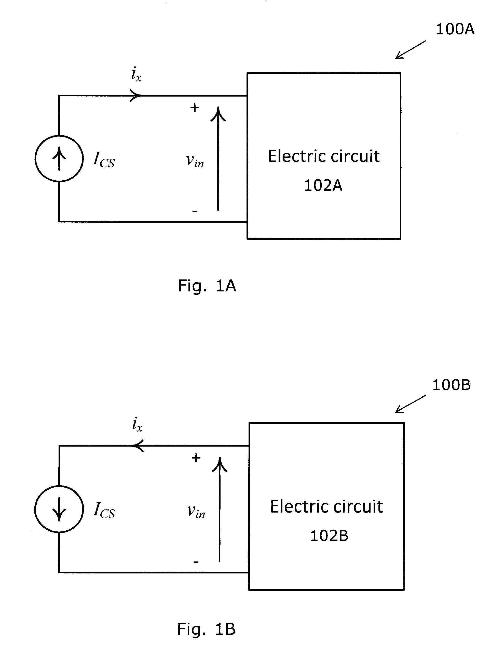
[0053]FIG. 1A shows the circuit 100A of a basic current source ICS. In FIG. 1A, the current source ICS is arranged to deliver electric current ix to an electric circuit 102A, independent of the voltage vin across the current source ICS.

[0054]FIG. 1B shows the circuit 100B of a basic current sink ICS. In FIG. 1B, the current sink ICS is arranged to absorb electric current ix from an electric circuit 102B, independent of the voltage vin across the current source ICS.

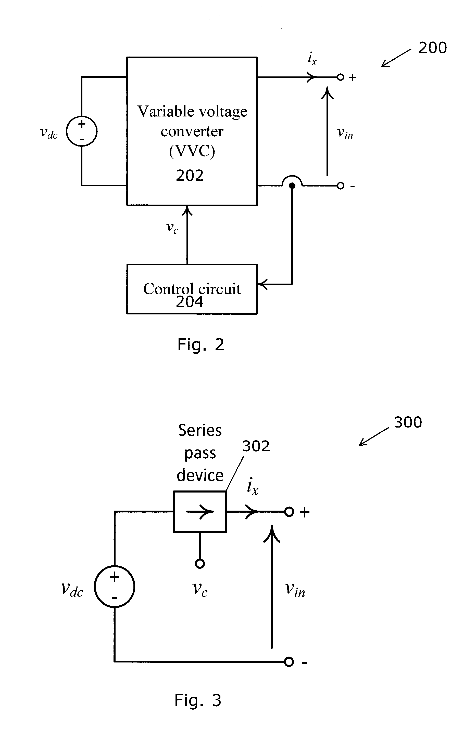
[0055]FIG. 2 shows a variable voltage converter (VVC) 202 and an associated control circuit 204 for realizing the current source ICS for delivering electrical energy to the external circuit 102A of FIG. 1A. As shown in FIG. 2, the variable voltage converter 202 is supplied by a voltage source vdc. The output current ix is regulated by controlling the output voltage of the variable voltage converter 202. In operation, the control circuit 204 first senses the output current ix and then generates and outputs necessary command...


PUM


Abstract

A current control apparatus arranged to regulate an electric current flowing between a load and an external electric circuit includes a current control loop having a current regulator arranged to manipulate an amount of the electric current flowing between the load and the external electric circuit; and a voltage control loop having a voltage regulator arranged to manipulate a voltage across the current regulator.

Description

TECHNICAL FIELD[0001]The present invention relates to a current control apparatus and particularly, although not exclusively, to a lossless active current source and / or current sink.BACKGROUND[0002]Current control circuits are often arranged between a current source and an electric circuit for absorbing electric current from the electric circuit or for delivering electric current to the electric circuit. Ideally, the current control circuits are operable to regulate current between the current source and the electric circuit, giving high dynamic response, low noise, and high energy efficient current control.[0003]Currently, these current control circuits either utilize a linear type series-pass device or a switched-mode power supply for current control.[0004]Linear type series pass devices can generally provide fast dynamic response, small output ripple current and low output noise, and they do not require output filters. However, series pass devices suffer from low energy efficienc...

Claims


Application Information

Patent Timeline
IPC IPC(8): G05F1/56G05F1/46
CPCG05F1/461G05F1/56G05F1/462G05F1/59H02M3/156H02M3/158H02M1/0009H02M1/0045H02M1/0087
Inventor CHUNG, SHU HUNG HENRYYUEN, KUEN FAATFANN, WING TO
Owner CITY UNIVERSITY OF HONG KONG
Why Eureka
Try Eureka