
Apparatus and Method for Bias-Free Branch Prediction

a branch prediction and branch prediction technology, applied in the field of computer processors, can solve the problems of increasing power consumption, increasing access latencies, and consequently limited prediction ability of forecasters, and achieves the effects of small correlation, greater prediction accuracy, and larger separation distances

Active Publication Date: 2015-12-17
WISCONSIN ALUMNI RES FOUND
View PDF15 Cites 13 Cited by
  • Summary
  • Abstract
  • Description
  • Claims
  • Application Information

AI Technical Summary

Benefits of technology

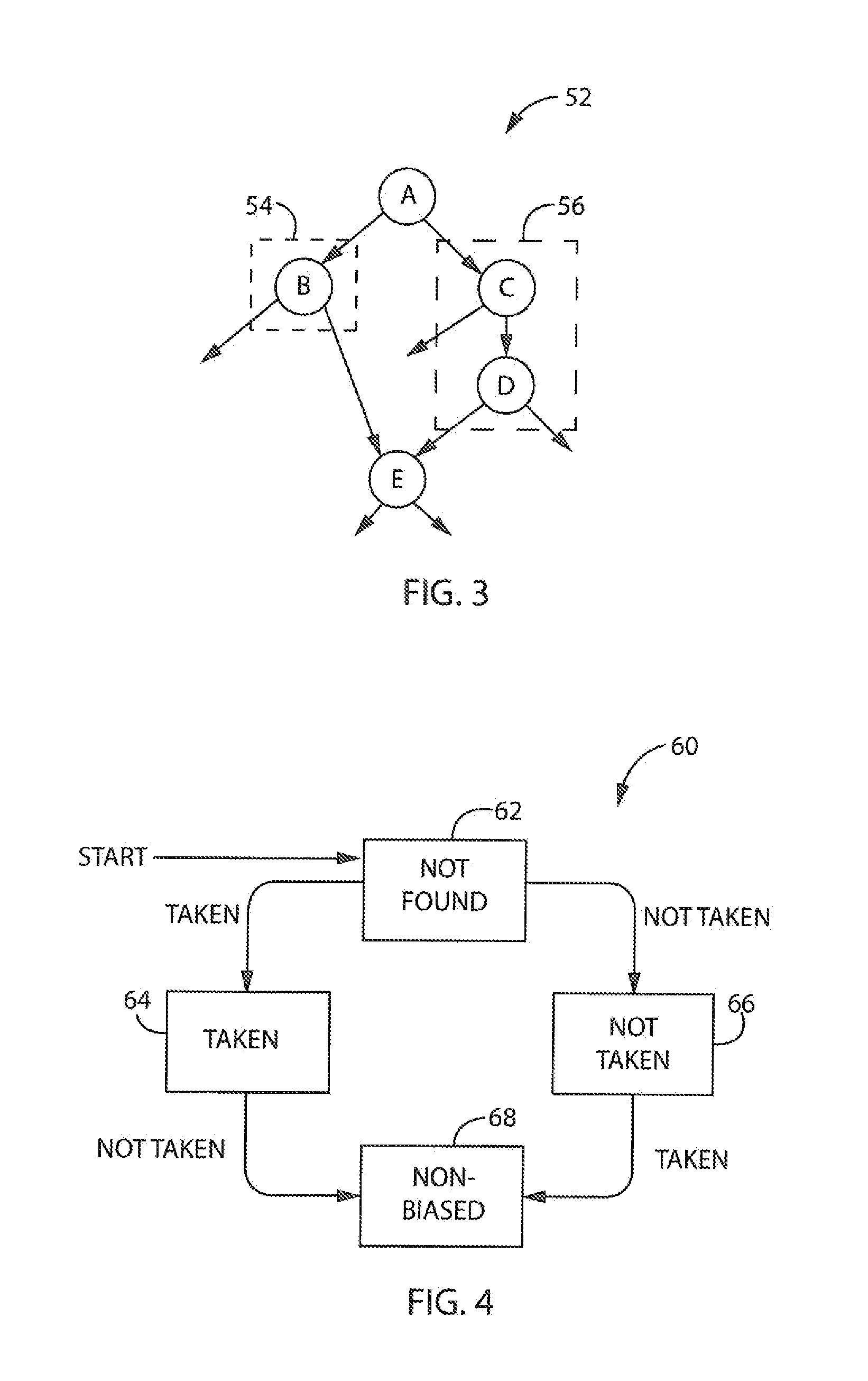
The invention recognizes that conditional branches in a program can be "biased," meaning they only show one behavior during execution. These branches can only reliably predict the outcome in the same direction as the original non-biased branch. The invention filters out biased branches to improve prediction accuracy and captures more distant correlations with non-biased branches. It also minimizes perturbations caused by new branches in the history buffer and provides a data structure for tracking and referencing branch states. The invention improves learning-based predictors and reduces the impact of initial training time. Overall, the invention enhances branch prediction accuracy and efficiency.

Problems solved by technology

However, systems with moderate hardware budgets, such as on the order of 32 to 64 KB, typically restrict such predictors from correlating beyond 32 to 64 branches in a dynamic execution stream.
As some correlations may only become evident over larger distances, such as on the order of 512 to 1024 branches apart, such predictors are consequently limited in their prediction ability.
However, such larger data structures undesirably result in increased access latencies and increased power consumption.
Also, such larger data structures undesirably cause increased training times for the neural-based perceptron predictors.

Method used


Image

  • Apparatus and Method for Bias-Free Branch Prediction
  • Apparatus and Method for Bias-Free Branch Prediction
  • Apparatus and Method for Bias-Free Branch Prediction

Examples


Embodiment Construction

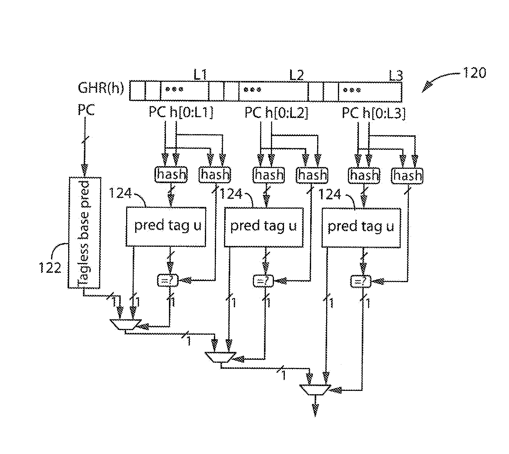
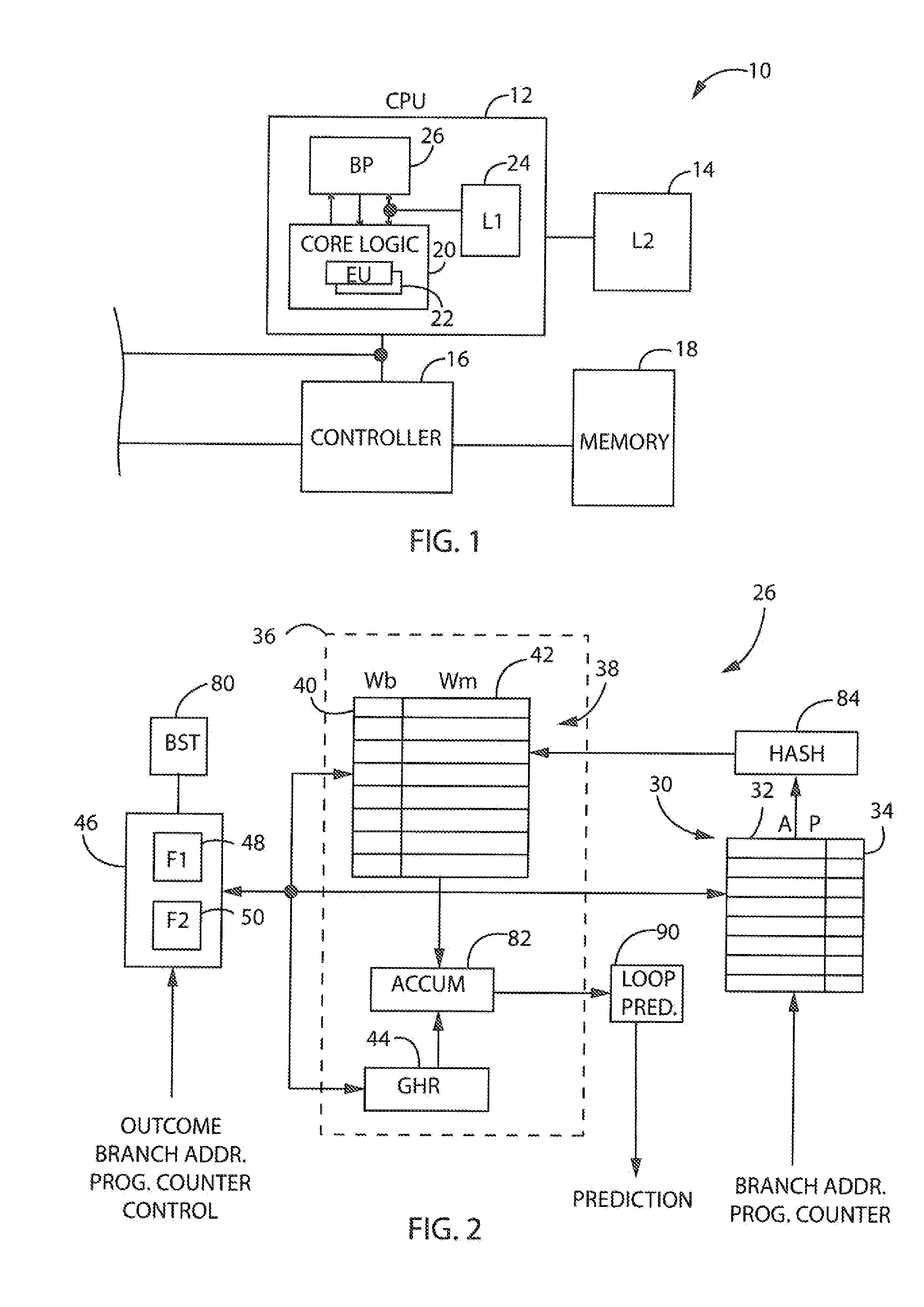
[0028]Retelling now to FIG. 1, an embodiment of the present invention will be described in the exemplar context of a computer system 10 and a processor 12. The processor 12 may be one of many processors in the computer system 10 and may include various interfaces and buses for communicating with external components, such as a cache 14, a memory controller 16 and a main memory 18. The processor 12 includes core logic 20 providing a plurality of execution units 22, which may be deeply pipelined, wide-issue execution units in a preferred embodiment. The processor 12 may also include a local cache 24 containing an instruction stream for processing and execution by the core logic 20 and the execution units 22. The instruction stream may be provided by hierarchical storage elements, including the cache 14 and the main memory 18 as directed by the memory controller 16, to achieve maximal performance as understood in the art.

[0029]The processor 12 further includes a branch prediction unit 2...


PUM


Abstract

Aspects of the present invention provide an apparatus and method for filtering biased conditional branches in a branch predictor in favor of non-biased conditional branches. Biased conditional branches, which are consistently skewed toward one direction or outcome, are filtered such that an increased number of non-biased conditional branches which resolve in both directions may be considered. As a result, more useful branches may be captured over larger distances, thereby providing correlations deeper in a global history to provide greater prediction accuracy. In addition, by tracking only the latest occurrences of non-biased conditional branches using a recency stack structure, even more distant branch correlations may be made.

Description

STATEMENT REGARDING FEDERALLY SPONSORED RESEARCH[0001]This invention was made with government support awarded by the National Science Foundation. The government has certain rights in the invention.BACKGROUND OF THE INVENTION[0002]The present invention relates to computer processors, and more particularly, to branch predictors for computer processors.[0003]In computer architecture, a branch predictor is a digital circuit that attempts to determine which direction a conditional branch may follow in an instruction stream. Branching is usually implemented with a conditional jump instruction, and once encountered, a branch may be “taken” or “not taken.” If taken, the instruction flow may continue in a first direction, and if “not taken,” the instruction flow may continue in a second direction. One example of a conditional branch is an “if-then-else” structure used in computer programming.[0004]High-performance processors, which tend to be deeply pipelined, typically rely on branch predic...

Claims


Application Information

Patent Timeline
IPC IPC(8): G06F9/38G06F9/30
CPCG06F9/30145G06F9/3806G06F9/3848G06F9/3844
Inventor LIPASTI, MIKKOGOPE, DIBAKAR
Owner WISCONSIN ALUMNI RES FOUND
Learn More