High frequency module

a high frequency module and module technology, applied in the direction of basic electric elements, electrical apparatus, semiconductor devices, etc., can solve problems affecting the performance of a high frequency circuit, and achieve the effect of power loss of a signal, which is, easily discharged

Inactive Publication Date: 2015-12-17
ALPS ALPINE CO LTD
View PDF5 Cites 0 Cited by
  • Summary
  • Abstract
  • Description
  • Claims
  • Application Information

AI Technical Summary

Benefits of technology

[0013]The embodiments of the present disclosure provide a high frequency module which can take an ESD measure without affecting performance of the high frequency circuit.
[0015]In the high frequency module which is configured in this way, the wiring conductor is disposed so as to intersect the side plate in a planar view, and thereby a value of a coupling capacitance between the wiring conductor and the side plate can be constant. As a result, it is possible to take an ESD measure without affecting performance of the high frequency circuit.
[0017]In the high frequency module which is configured in this way, an angle which is formed by the wiring conductor and the side plate is a right angle, and thereby an area at which the wiring conductor and the side plate intersect each other can be reduced in a minimum manner. For this reason, a value of a coupling capacitance between the wiring conductor and the side plate can be smallest, and a high frequency circuit can be easily designed.
[0019]In the high frequency module which is configured in this way, it is possible to accurately set a separation distance between the wiring conductor and the side plate.
[0021]In the high frequency module which is configured in this way, in a case in which the antenna is coupled to the wiring electrode, power loss of a signal which is transmitted to or received from the antenna can be reduced, and static electricity can be easily discharged.
[0022]In a high frequency module of the present disclosure, a wiring conductor is disposed so as to intersect a side plate in a planar view, and thereby a value of a coupling capacitance between the wiring conductor and the side plate can be constant. As a result, it is possible to take an ESD measure without affecting performance of a high frequency circuit.

Problems solved by technology

However, being generally capacitive, an ESD protection element affects performance of a high frequency circuit.
However, in a case in which an ESD measure for an electronic circuit unit 900 which is disclosed in Japanese Unexamined Patent Application Publication No. 2012-018857 is used for a wiring electrode for a high frequency circuit of a high frequency module, there is the following problem.

Method used


Image

  • High frequency module
  • High frequency module
  • High frequency module

Examples


Embodiment Construction

[0027]The following description is intended to convey a thorough understanding of the embodiments described by providing a number of specific embodiments and details involving a pressure detection device and intake pressure measurement apparatus. It should be appreciated, however, that the present invention is not limited to these specific embodiments and details, which are exemplary only. It is further understood that one possessing ordinary skill in the art, in light of known systems and methods, would appreciate the use of the invention for its intended purposes and benefits in any number of alternative embodiments, depending on specific design and other needs.

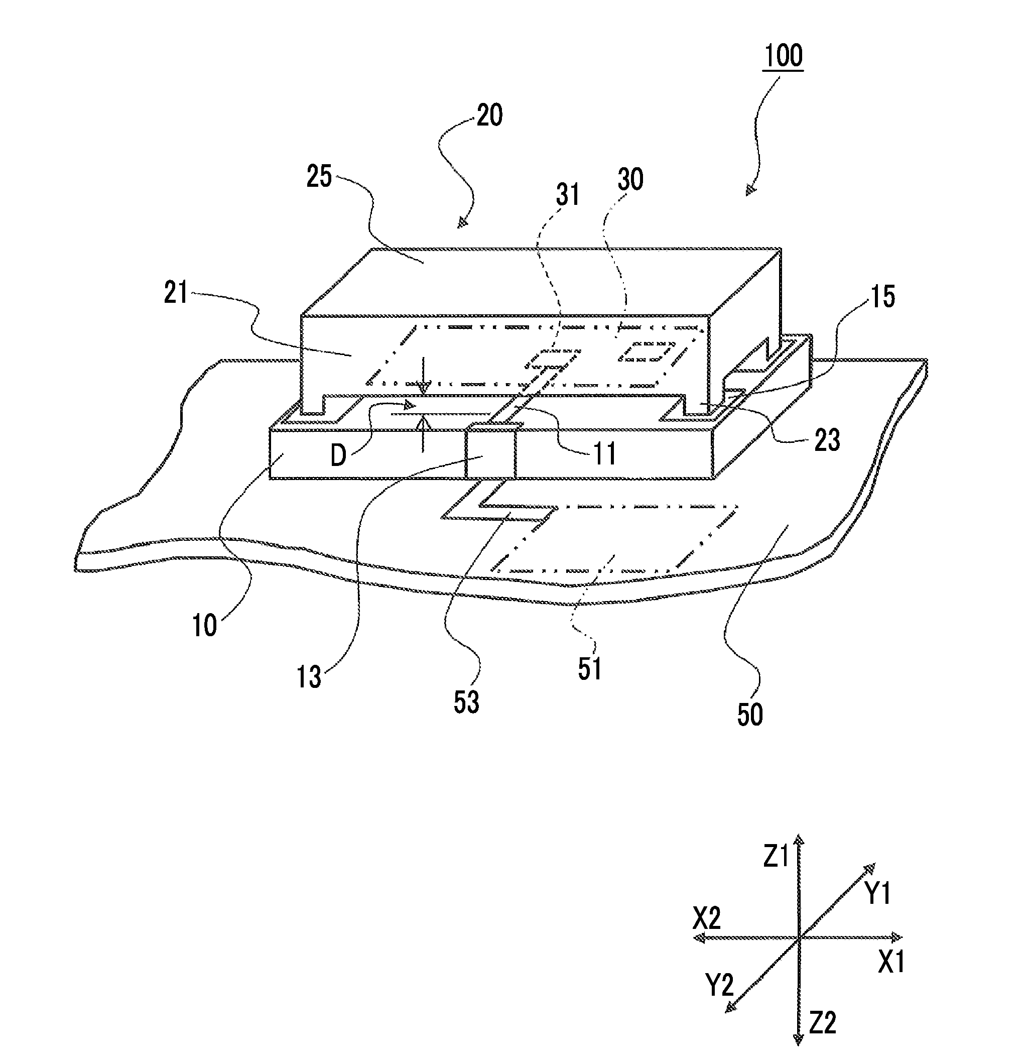
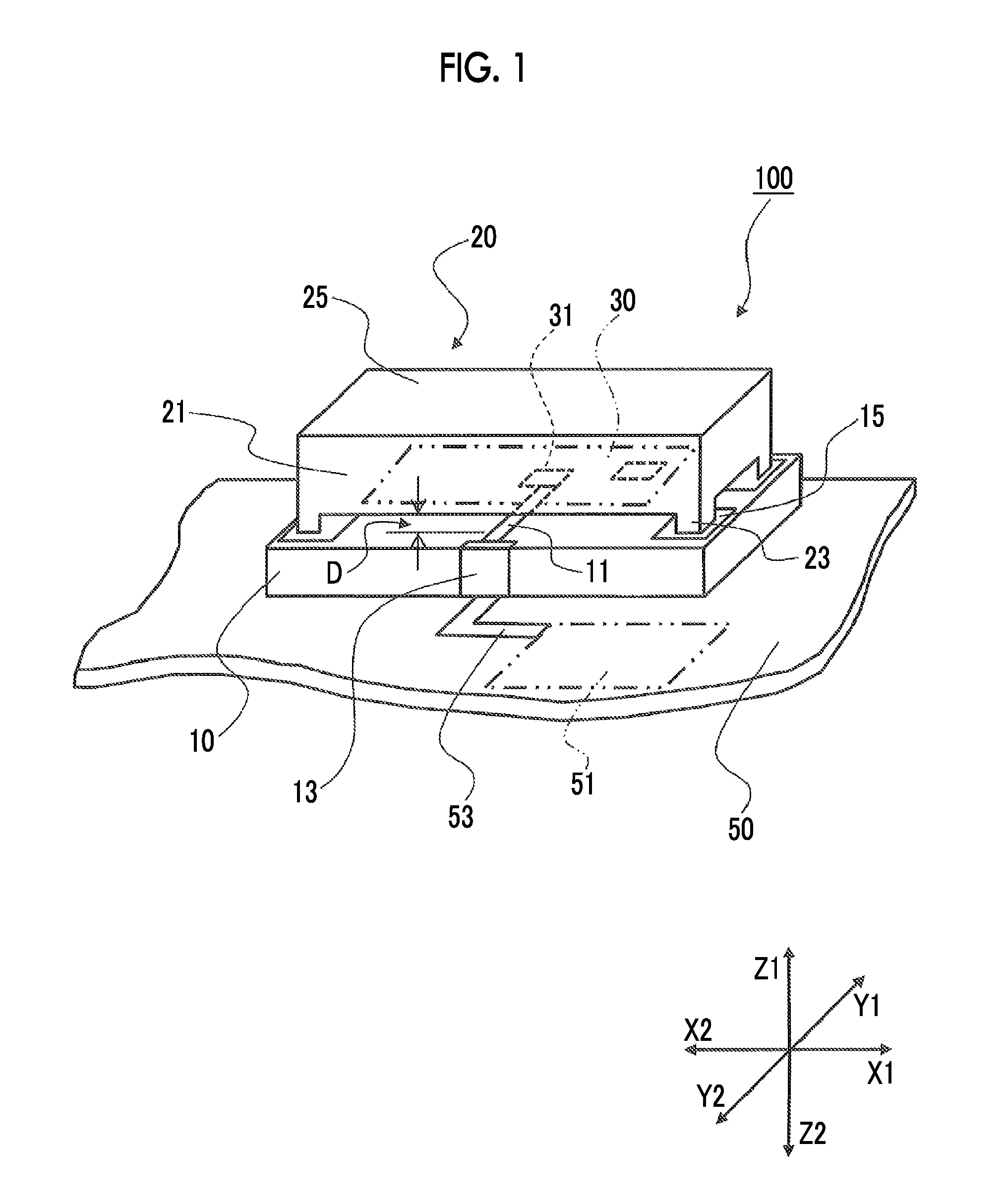
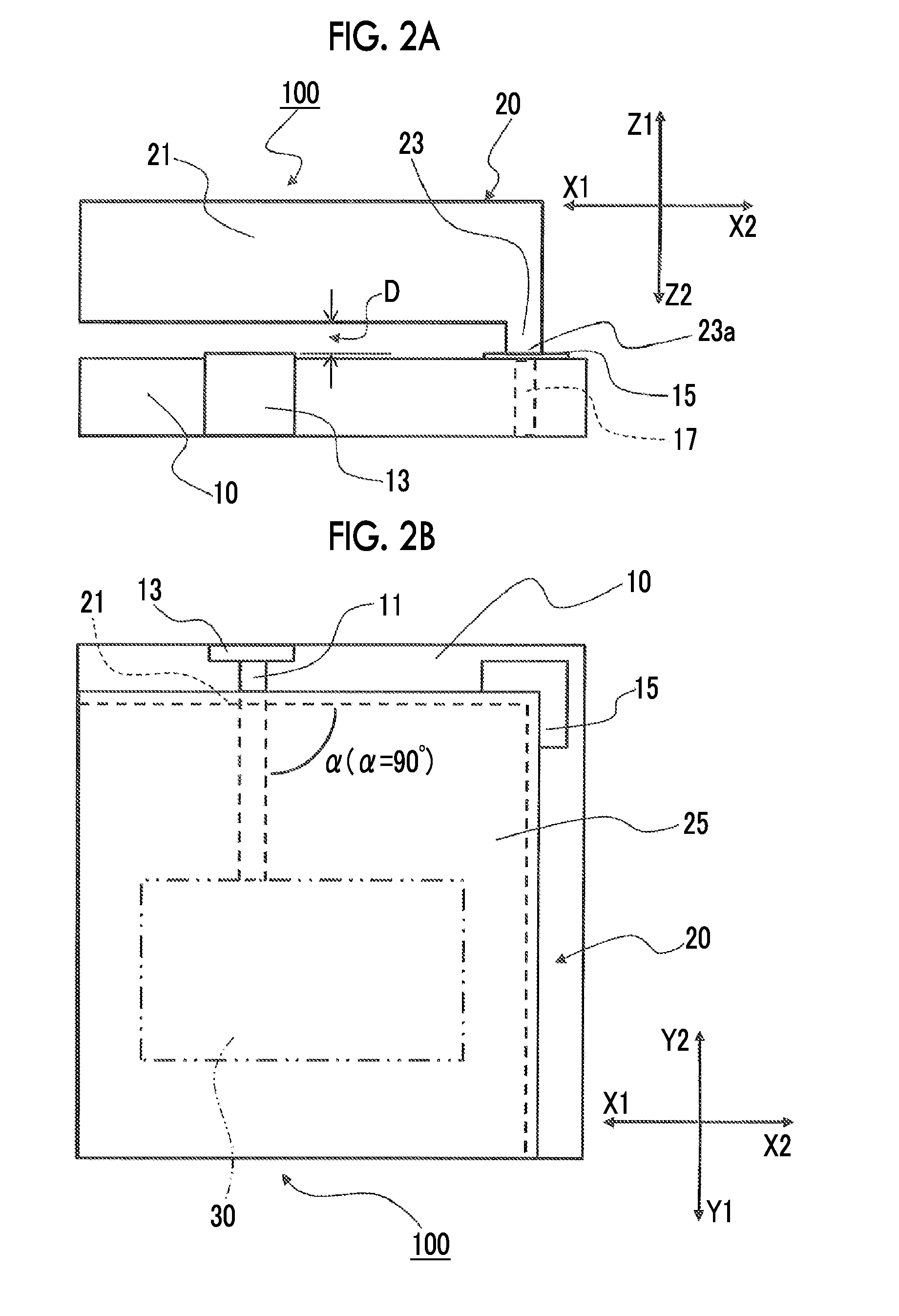
[0028]Hereinafter, an embodiment of the present invention will be described with reference to the drawings. Meanwhile, in the present specification, unless otherwise noted, X1 of each drawing is referred to as a right side, X2 of each drawing is referred to as a left side, Y1 of each drawing is referred to as a far side, Y2...


PUM


Abstract

A high frequency module includes a wiring substrate and a metal shield cover. A wiring conductor through which a high frequency signal is transferred and which is coupled to the electronic component, a wiring electrode which is coupled to the wiring conductor and is provided in an outside further than the shield cover, and a ground electrode which is coupled to the shield cover, are provided on the wiring substrate. The shield cover includes a side plate which is formed of a metal of a plate shape, and a leg portion which is provided in the side plate and is soldered to the ground electrode. A gap is formed between the side plate and the wiring substrate, and the wiring conductor is disposed so as to intersect the side plate in a planar view, on the wiring substrate which is positioned below the gap.

Description

CLAIM OF PRIORITY[0001]This application contains subject matter related to and claims the benefit of Japanese Patent Application No. 2014-120556, filed on Jun. 11, 2014, the entire contents of which is incorporated herein by reference.BACKGROUND OF THE DISCLOSURE[0002]1. Field of the Disclosure[0003]The present disclosure relates to a high frequency module, and particularly to a high frequency module which can prevent damage due to static electricity discharge to an electronic component.[0004]2. Description of the Related Art[0005]In recent years, for a high frequency module in which a high frequency circuit such as a wireless LAN is mounted, an ESD protection element for taking an electro-static discharge (ESD) measure has been used. However, being generally capacitive, an ESD protection element affects performance of a high frequency circuit. Thus, it is desirable that a high frequency module takes an ESD measure, without using an ESD protection element which affects performance o...

Claims


Application Information

Patent Timeline
Patent Type & Authority Applications(United States)
IPC IPC(8): H02H9/04
CPCH02H9/044H01L23/60H01L23/66H01L2924/0002H01L2924/00
Inventor SUGAWARA, JUNFURUYAMA, YOSHIKAZU
Owner ALPS ALPINE CO LTD
Why Eureka
Try Eureka