Method for the producing of a floor covering

a technology for floor coverings and manufacturing methods, applied in the direction of adhesive types, building components, lamination, etc., can solve the problems of deterioration of the surface coating properties, slight shrinkage, fouling problems, etc., and achieve the effect of not deteriorating the appearance or surface properties of the covering

Inactive Publication Date: 2005-02-01
GERFLOR
View PDF14 Cites 0 Cited by
  • Summary
  • Abstract
  • Description
  • Claims
  • Application Information

AI Technical Summary

Benefits of technology

The viscosity of the bead of mastic is between 10 000 and 12 000 centipoise (cps) at 1000 rpm, thereby allowing it to be deposited in a uniform manner, not only horizontally but also for making a vertical bond, for example to produce a plinth upturn.
By proceeding in this way, a perfect sealed joint is obtained between two consecutive widths, without any deterioration in the appearance or the surface properties of the covering.

Problems solved by technology

One of the problems that arises with such coverings, which are adhesively bonded to the backing, is that of how to produce the join between two consecutive strips or panels, and how to seal along plinth-like upturned edges.
However, the competence of the bonder is of primary importance for obtaining good uniformity of the joint and above all it results in deterioration of the properties of the surface coating with, especially in the case in which the latter is formed by a varnish, a “shriveling” defect that may extend over more than one centimeter of width.
Moreover, when producing a joint, after leveling in order to remove excess material, a slight shrinkage very often occurs, forming a recess at the bonded joint that will cause fouling problems during use.
However, the join between two consecutive widths is weaker than in the case of hot bonding, the strength not exceeding 4 daN / cm.
In addition, it is not possible to achieve bonding in corners or in a plinth upturn on account of the low viscosity of the solution which also involves the use of a solvent.
Such a technique therefore involves four successive operations after bonding the covering to the floor and it is difficult to check the uniformity of the bond after formation.

Method used


Image

  • Method for the producing of a floor covering
  • Method for the producing of a floor covering
  • Method for the producing of a floor covering

Examples


Embodiment Construction

The invention employed for laying a floor covering, comprising a wear layer having a thickness of 0.7 mm, made of plasticized PVC reinforced with a nonwoven mat combined with a glass mesh, and a surface coating based on a crosslinked polyurethane, consisting of a film giving the material its ultraviolet, abrasion and wear resistance properties.

This complex is combined with a foam underlay. The total thickness is 3.2 mm.

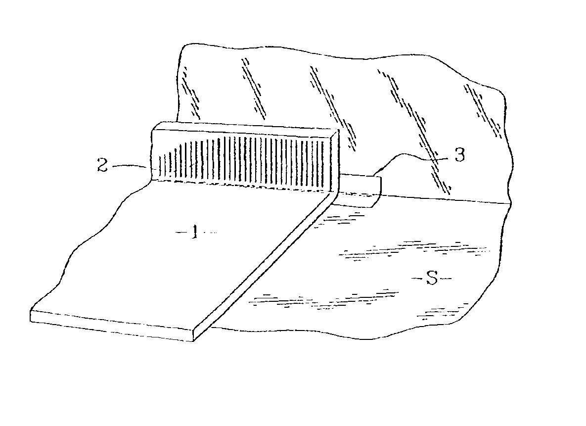
In a first phase of installing such a covering as shown in FIG. 1, a first width (1) is stuck to the floor (S) using an acrylic adhesive in emulsion form, deposited using a spatula.

The plinth-like upturn (2) is also formed by adhesive bonding, an angle piece (3) being provided in the corner.

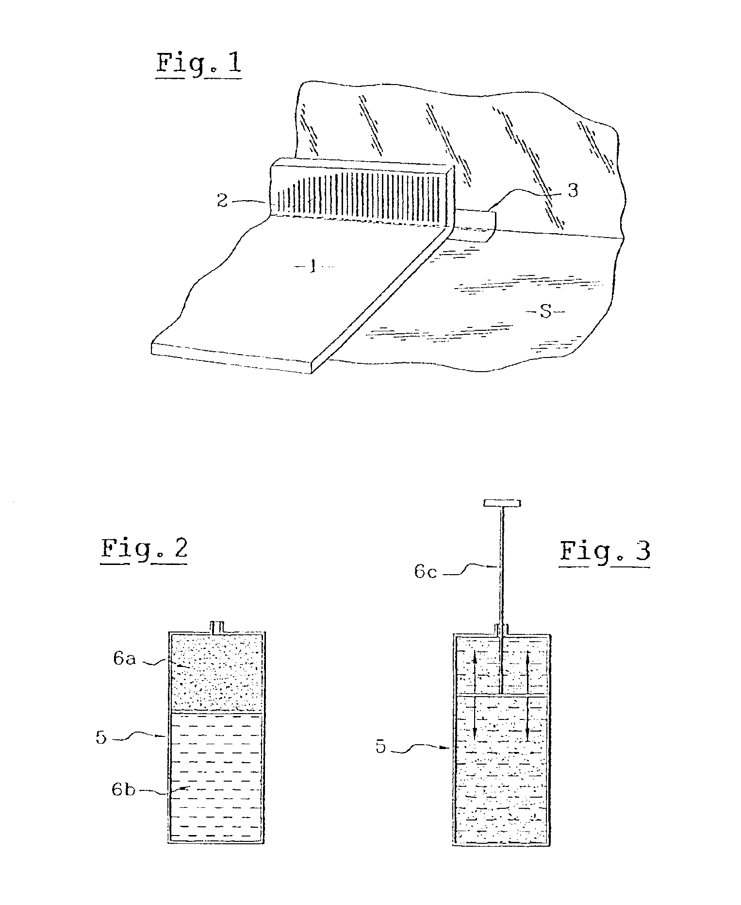
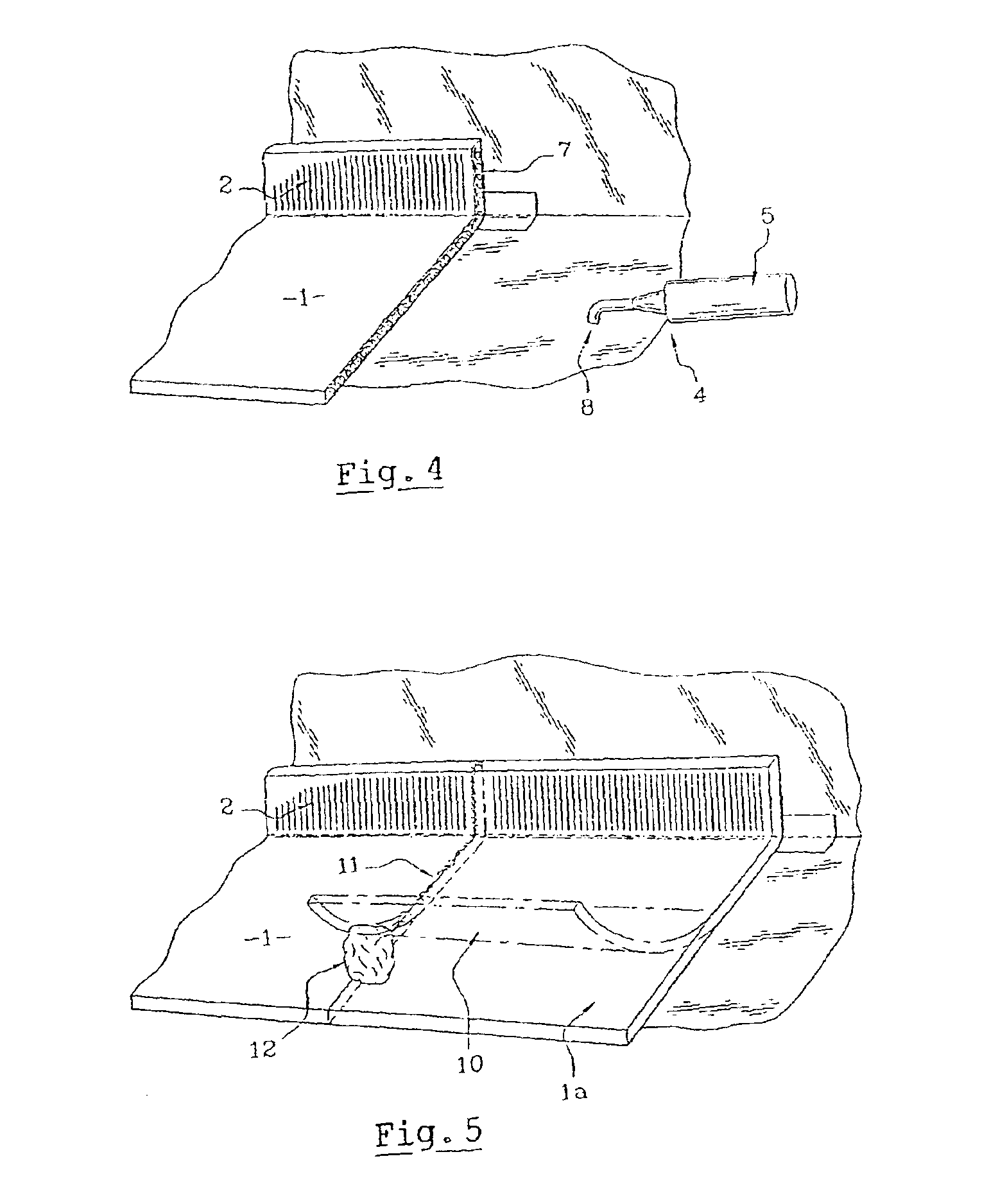
Once this first width (1) has been laid, a bead of adhesive (7) is deposited as shown in FIG. 4, using a gun (4) holding a cartridge (5), along the entire length of the width laid.

Refering to FIG. 2, the cartridge (5) contains the hardener (6a), namely an aliphatic isacyanate and t...


PUM

PropertyMeasurementUnit
viscosityaaaaaaaaaa
viscosityaaaaaaaaaa
widthaaaaaaaaaa

Abstract

The invention relates to a method for laying a floor covering that includes a flexible material containing a thermoplastic wear layer made from, in particular, plasticized PVC. The basic panels that form the covering are glued to the ground and cold welded in between on the site to be covered. After a panel has been positioned and glued to the surface to be covered, a continuous bead of mastic, which is made on the actual site by mixing a hardener and a polyurethane resin in aqueous phase, is applied laterally along the entire depth of the covering. The next panel is positioned on the ground which is covered with adhesive and the lateral edge thereof is pinned against the edge of the preceding panel comprising the bead of mastic, thereby causing the excess material to come to the surface, where it is removed by simply wiping with water.

Description

TECHNICAL FIELDThe present invention relates to an improvement to methods for producing floor coverings from flexible sheet materials.It relates more precisely to an improved method for producing the join between elementary panels.PRIOR ARTIt was proposed a very long time ago to produce floor coverings from flexible sheets of plastic, in particular plasticized PVC, optionally reinforced by a fabric structure embedded within the mass of the material.Moreover, to improve comfort, the thermoplastic surface sheet is very often combined with a foam underlay. In addition, the visible face is covered with a top coat giving the whole assembly specific properties such as UV resistance, crush resistance, scratch resistance, wear resistance, abrasion resistance and nonskid properties.One of the problems that arises with such coverings, which are adhesively bonded to the backing, is that of how to produce the join between two consecutive strips or panels, and how to seal along plinth-like uptur...

Claims


Application Information

Patent Timeline
Patent Type & Authority Patents(United States)
IPC IPC(8): C09J175/04C09K3/10E04F15/16E04F15/02
CPCC09J175/04E04F15/16E04F15/02C09K3/1021C08G2170/80
Inventor RIVAT, ALAINHINAULT, ROBERT
Owner GERFLOR
Why Eureka
Try Eureka