Vial shield

Active Publication Date: 2015-12-24
JMS CO LTD
View PDF3 Cites 53 Cited by
  • Summary
  • Abstract
  • Description
  • Claims
  • Application Information

AI Technical Summary

Benefits of technology

[0011]Attaching the vial shield of the present invention to the vial bottle makes it possible to reduce escape of a drug and a drug solution within the vial bottle to

Problems solved by technology

Therefore, the possibility that the drugs and the drug solut

Method used


Image

  • Vial shield
  • Vial shield
  • Vial shield

Examples


Example

Embodiment 1

Configuration of Vial Shield

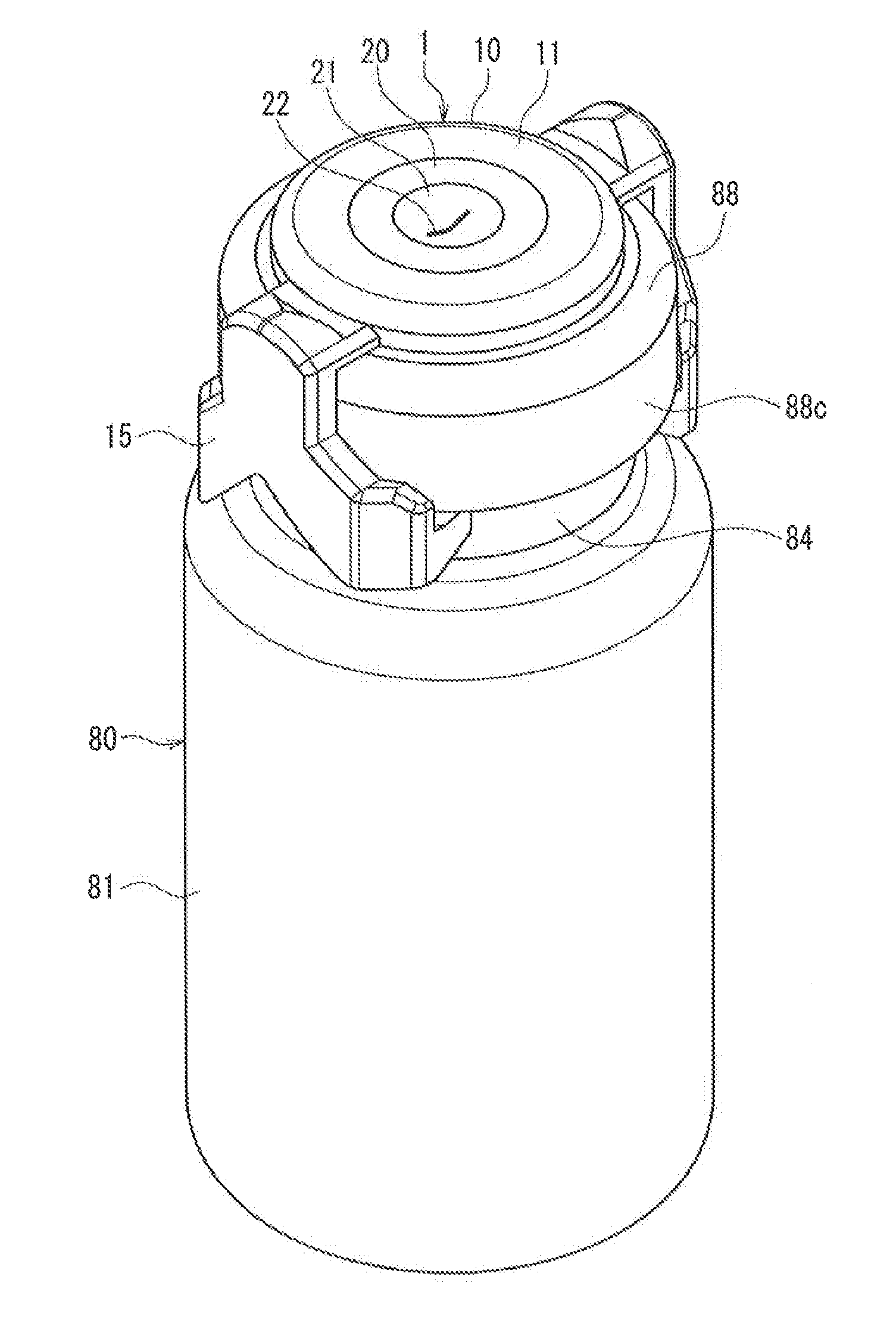
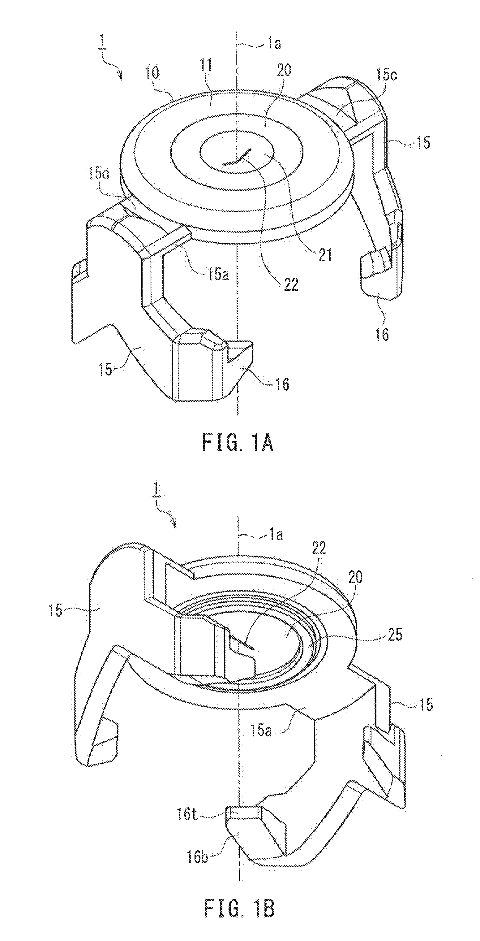
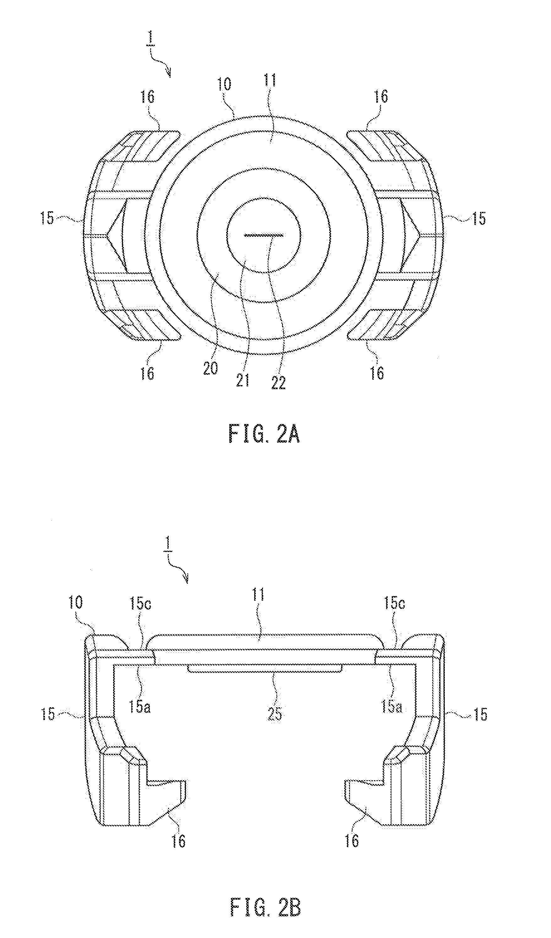
[0048]FIG. 1A is a perspective view of a vial shield 1 according to Embodiment 1 of the present invention when viewed from above, and FIG. 1B is a perspective view of the vial shield 1 when viewed from below. FIG. 2A is a plan view of the vial shield 1, and FIG. 2B is a side view of the vial shield 1. FIG. 3 is a cross-sectional perspective view of the vial shield 1 taken along a plane containing a central axis 1a of the vial shield 1. FIG. 4 is an exploded perspective view of the vial shield 1. For the sake of convenience of the following description, a direction that is parallel to the central axis 1a of the vial shield 1 is referred to as “vertical direction”, the upper side of the paper plane in FIG. 2B is referred to as “upper side” of the vial shield 1, and the lower side of the paper plane in FIG. 2B is referred to as “lower side” of the vial shield 1. A direction that is parallel to a plane perpendicular to the central axis 1a is refer...

Example

Embodiment 2

Configuration of Vial Shield

[0108]FIG. 14A is a perspective view of a vial shield 2 according to Embodiment 2 of the present invention when viewed from above, and FIG. 14B is a perspective view of the vial shield 2 when viewed from below. FIG. 15 is a cross-sectional perspective view of the vial shield 2 when viewed from above taken along a plane containing a central axis 2a of the vial shield 2 and line 15-15 in FIG. 14A. FIG. 16A is a cross-sectional perspective view of the vial shield 2 when viewed from above taken along a plane containing the central axis 2a and line 16-16 in FIG. 14A. FIG. 16B is a cross-sectional perspective view of the vial shield 2 when viewed from below taken along the plane containing the central axis 2a and line 16-16 in FIG. 14A. FIG. 17 is an exploded perspective view of the vial shield 2. For the sake of convenience of the following description, the “vertical direction”, the “upper side”, the “lower side”, the “horizontal direction”, the “c...


PUM


Abstract

A vial shield (1) has a shield main body (10) and a valve element (20). The shield main body (10) includes an annular top plate (11) that is to be laid on top of an upper surface of a stopper (86) that seals a mouth (83) of the vial bottle (80), a plurality of legs (15) extending downward from the top plate (11), and a plurality of claws (16) provided in the plurality of legs (15), the claws being engageable with the mouth (83) of the vial bottle (80). The valve element (20) blocks an opening at the center (12) of the top plate (11). A cut (22) passing through the valve element (20) in a vertical direction is formed in the valve element (20).

Description

TECHNICAL FIELD[0001]The present invention relates to a vial shield that is to be put over a stopper of a vial bottle.BACKGROUND ART[0002]Drugs in powder form are generally distributed in vial bottles in which the drugs are sealed in a gas-tight manner. To administer such a drug to a patient, a solvent is injected into the vial bottle, the drug is dissolved in the solvent to obtain a drug solution, and then the drug solution is transferred from the vial bottle into a drug solution bag. After that, the drug solution within the drug solution bag is administered to the patient. The injection of the solvent into the vial bottle and the extraction of the drug solution from the vial bottle are performed by piercing a stopper (rubber stopper) that seals a mouth (opening) of the vial bottle with a piercing needle (sometimes referred to as “bottle needle”).[0003]There are cases where the drug contained in the vial bottle is a drug that is designated as a powerful drug like an anticancer agen...

Claims


Application Information

Patent Timeline
IPC IPC(8): A61J1/22A61J1/20A61J1/14
CPCA61J1/22A61J1/2048A61J1/1412A61J1/1406A61J1/1425A61J1/2044A61J1/2096B65D51/002
Inventor NOGUCHI, YUSUKETAKEUCHI, MASAHIKO
Owner JMS CO LTD
Why Eureka
Try Eureka