Roller burnishing tool device

a tool device and rolling tool technology, applied in the direction of burnishing machines, manufacturing tools, metal-working equipment, etc., can solve the problems of complex structure of the housing, large outer diameter of the housing, and restricted attachment of the processing machine, so as to reduce the number of parts and simplify the structure of the housing. , the effect of improving the maintenance performan

Active Publication Date: 2015-12-24
SUGINO MACHINE
View PDF0 Cites 1 Cited by
  • Summary
  • Abstract
  • Description
  • Claims
  • Application Information

AI Technical Summary

Benefits of technology

[0030]According to the above preferable constitution, the present invention includes the biasing force adjusting tool, so that the pressing force in burnishing can be properly adjusted. Therefore, a uniformly finished surface can be made.
[0031]The roller burnishing tool device according to the present invention simplifies the constitution thereof to reduce the number of parts and to be miniaturized. Furthermore, maintenance performance can be improved and a uniformly finished surface can be made.

Problems solved by technology

However, in the roller burnishing tool device described in the patent literature 1, the displacement mechanism is disposed in the housing, so that the structure of the housing is complex and the outer size of the housing is large.
Therefore, there has been a problem that an attachable processing machine is restricted.
Nevertheless, there has been a problem that maintenance is hard to be performed because the structure of the housing is complex.

Method used


Image

  • Roller burnishing tool device
  • Roller burnishing tool device
  • Roller burnishing tool device

Examples


Embodiment Construction

[0037]A roller burnishing tool device according to an embodiment of the present invention will be described in detail appropriately with reference to the attached drawings.

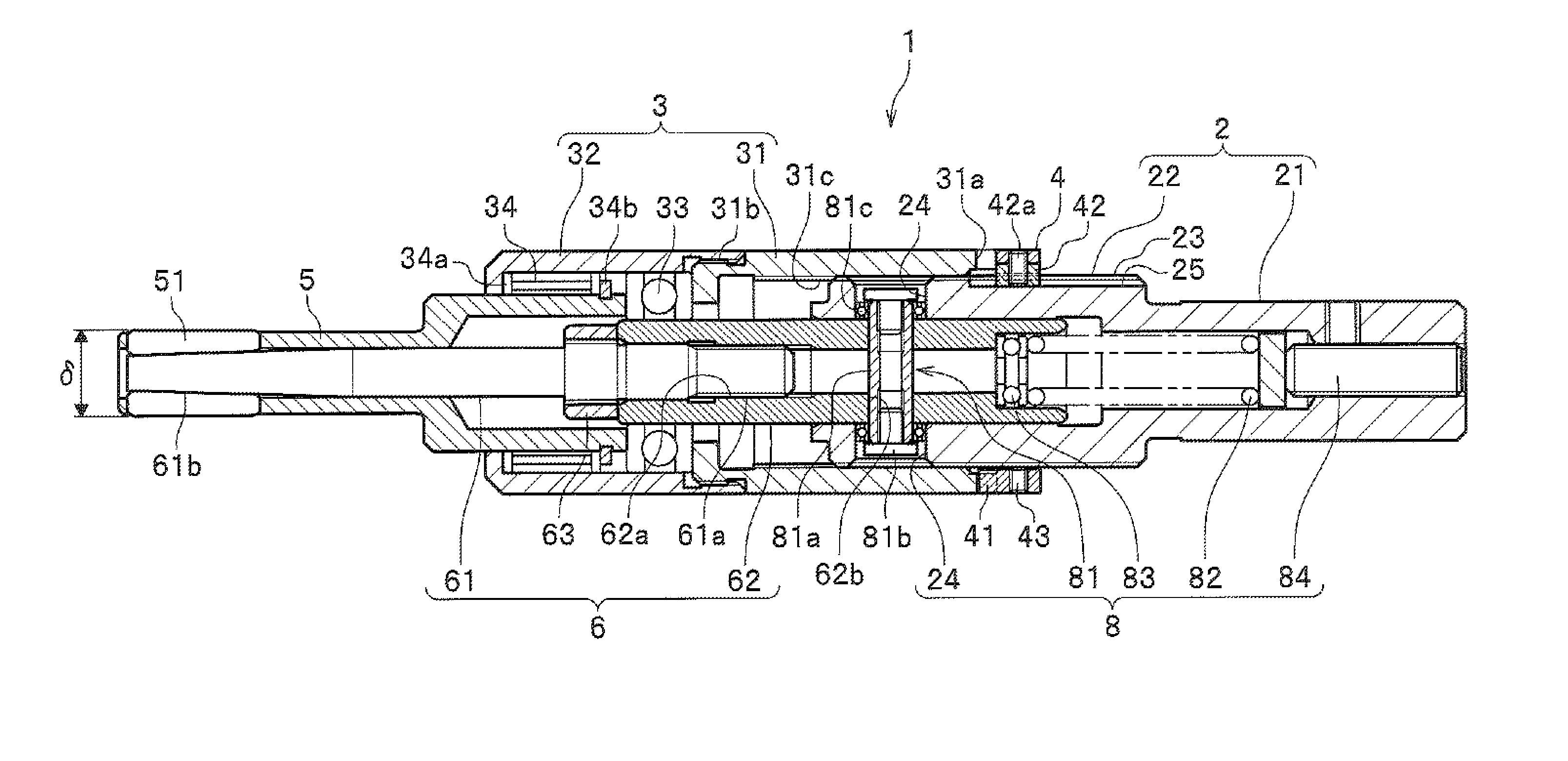
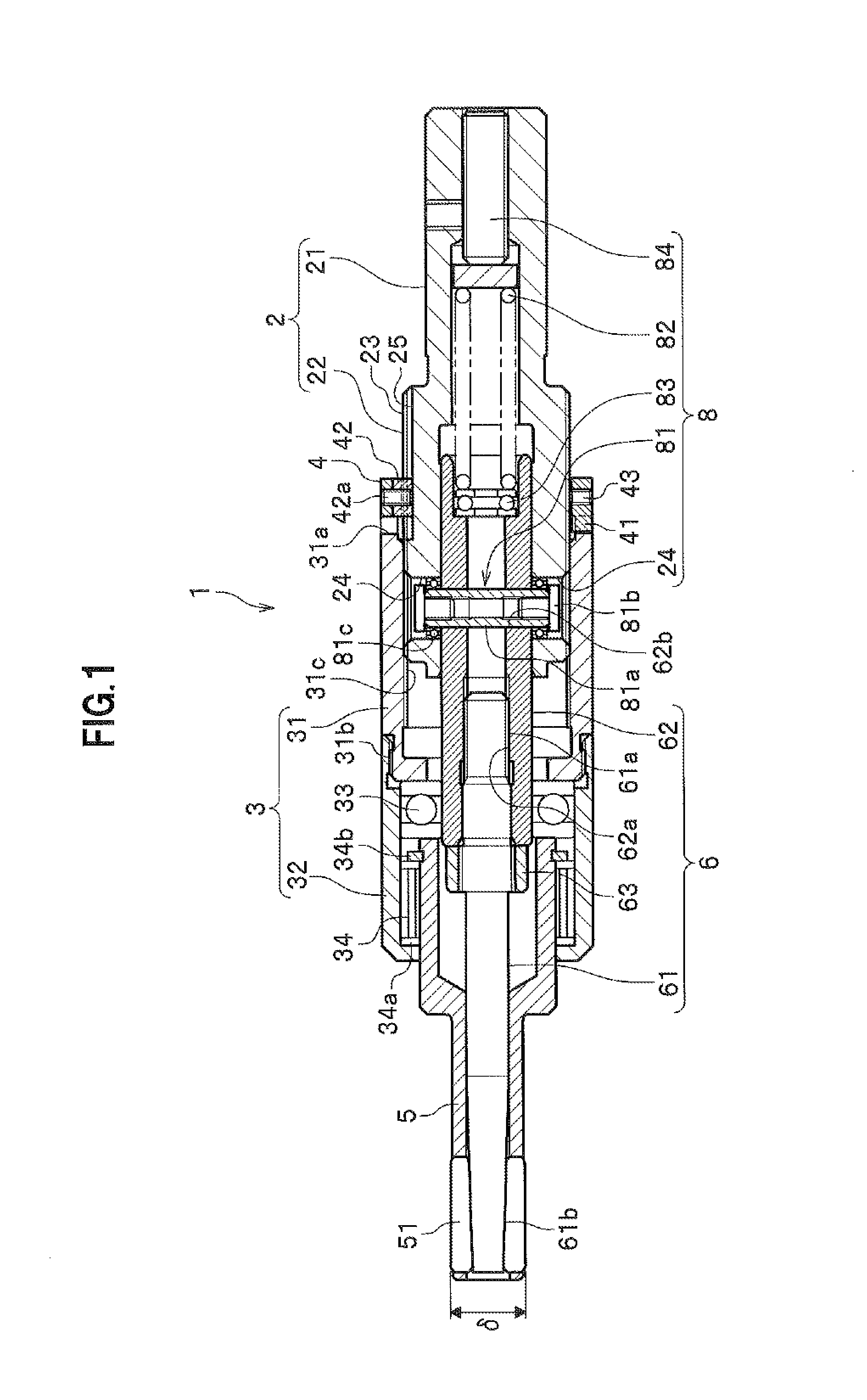
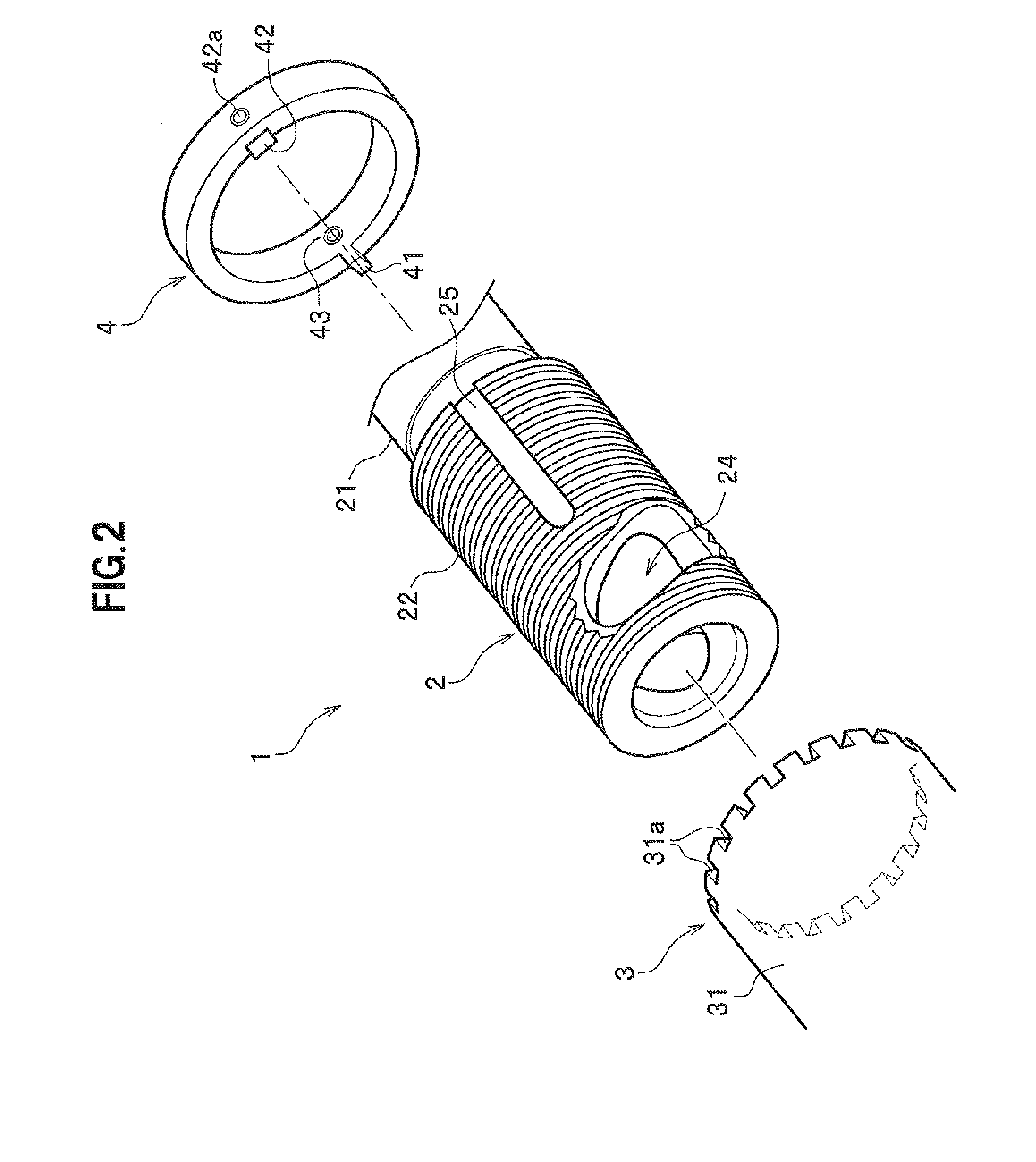
[0038]As shown in FIG. 1, the roller burnishing tool device 1 is equipped with a shank 2, a housing 3, an adjustment ring 4, a frame 5, a plurality of tapered rollers 51, a mandrel 6, and a tool diameter following mechanism 8. The shank 2 is to be attached to a processing machine (not shown) to be rotated. The housing 3 is connected to the shank 2. The adjustment ring 4 connects the shank 2 and the housing 3. The frame 5 is a roller support member to support the tapered rollers 51, and a hollow member with an annular shape (circle) in a cross section thereof. The tapered rollers 51 are supported to rotate by the roller support member 5. The mandrel 6 has a tapered portion 61b matched with the tapered shape of each of the tapered rollers. The tool diameter following mechanism 8 connects the shank 2 and the mandrel ...


PUM

PropertyMeasurementUnit
diameteraaaaaaaaaa
diameteraaaaaaaaaa
biasing forceaaaaaaaaaa

Abstract

Provided is a roller burnishing tool device including a shank; a housing connected to the shank, a connected position of the housing relative to the shank being adjustable; a roller support member supported to be capable of rotating relative to the housing and attached to follow a movement of the housing in a case of adjusting the connected position; tapered rollers supported by the roller support member; a mandrel having a tapered portion matched with the tapered rollers and movable relative to the roller support member; and a tool diameter following mechanism connecting the shank and the mandrel, having a lead groove formed spirally in a front portion of the shank, a pin member capable of moving along the lead groove, a pin member insertion hole formed in the mandrel to insert the pin member therein, and a biasing unit biasing the mandrel forward.

Description

CROSS REFERENCE TO RELATED APPLICATION[0001]This application claims the foreign priority benefit under Title 35, United States Code, 119 (a)-(d) of Japanese Patent Application No. 2014-129287, filed on Jun. 24, 2014 in the Japan Patent Office, the disclosure of which is herein incorporated by reference in its entirety.BACKGROUND OF THE INVENTION[0002]1. Technical Field[0003]The present invention relates to a roller burnishing tool device, especially to a roller burnishing tool device equipped with a tool diameter following mechanism.[0004]2. Description of Background Art[0005]A roller burnishing tool device is a device which presses a roller or rollers, while rotating the roller or the rollers, onto a workpiece, for example, onto an inner surface of a cylindrical hole of the workpiece, to plastically deform and finish the surface to be a mirror surface. The finishing by using the roller burnishing tool device is affected by a variation of the diameter of the hole to be processed or ...

Claims


Application Information

Patent Timeline
Patent Type & Authority Applications(United States)
IPC IPC(8): B24B39/00
CPCY10T29/471B24B39/00
Inventor MIYAUCHI, SHINYAFUTAMURA, MASARU
Owner SUGINO MACHINE
Why Eureka
Try Eureka