Braking system and method for dimensioning a braking system

a braking system and dimensioning technology, applied in the field of braking system technology, can solve the problems of reducing the delivery capacity of the pump element, reducing the speed further, and causing the braking system to produce a high hydraulic pressure, so as to reduce the total demand on the motor element, reduce the torque or motor torque, and reduce the effect of pressur

Active Publication Date: 2015-12-24
ROBERT BOSCH GMBH
View PDF2 Cites 11 Cited by
  • Summary
  • Abstract
  • Description
  • Claims
  • Application Information

AI Technical Summary

Benefits of technology

[0014]To now relieve a motor element, a separating element may be provided, which, for example, in the case of a dual-circuit braking system having a brake-circuit partial circuit for a first axle and a second axle, for example, a front axle and a rear axle, decouples a brake-circuit partial circuit from the pressure application by, for example, the brake pedal of a partial brake-by-wire system. In this way, a lower hydraulic line pressure will usually occur in the decoupled brake-circuit partial circuit than in the non-decoupled brake-circuit partial circuit. Since a motor element regularly jointly supplies the separate pump elements of the two brake-circuit partial circuits, because of the reduced pressure in one brake-circuit partial circuit, the total demand on the motor element is reduced. Due to the reduced torque or motor torque resulting therefrom, a higher speed results for the motor element. The operating point of the motor element therefore shifts from the worst-case operating point or the extremal operating point, at which sufficient braking power is still available, to an operating point which relieves the motor element in relation to the extremal ABS operating point. Extremal is to be understood hereafter as a state in which an element may just still fulfill a required function.
[0015]In other words, this means that the motor element is no longer operated at its limit, however, but rather that reduced demands are placed on the motor element. These reduced demands now enable the motor element to be altered in such a way that this motor element, also in the operating state having the actually reduced demands, is again operated at its extremal operating point, therefore at the limit. Such a shift of the operating point may be taken into consideration in the dimensioning of a special braking system in that, for example, a motor element having a lower delivery capacity is provided, which results in a cost reduction for the braking system, for example. Similarly, such an altered motor element may have a lower weight, for example. A lower weight generally also means lower fuel consumption for a vehicle.
[0016]Alternatively, at least one pump element may be altered, while the motor element is essentially maintained, so that the operating point of the motor element does again fall to the extremal operating point, but a delivery capacity of a pump element in the hydraulic system increases. Such an increase of the delivery capacity in turn positively influences the pressure buildup dynamics of a braking system. In other words, by way of the targeted load of a motor element, a previously performed relief, for example, by disconnection or separation of a brake-circuit partial circuit, is used to be able to provide pump elements, which thus provide the braking system with higher dynamics, which in turn has a positive effect on the pedestrian protection.

Problems solved by technology

A comparatively low pedal pressure or no pedal movement at all may thus induce a high hydraulic pressure in the braking system.
In other words, it must be ensured in such a worst-case brake scenario that this operating point is not exceeded, in particular that a higher motor torque does not occur, which would result in a speed reduced still further, whereby a delivery capacity of a pump element would possibly be too low to build up a desired brake pressure.

Method used


Image

  • Braking system and method for dimensioning a braking system
  • Braking system and method for dimensioning a braking system
  • Braking system and method for dimensioning a braking system

Examples


Embodiment Construction

[0020]One exemplary embodiment of a braking system according to the present invention will be described in greater detail with reference to FIG. 1.

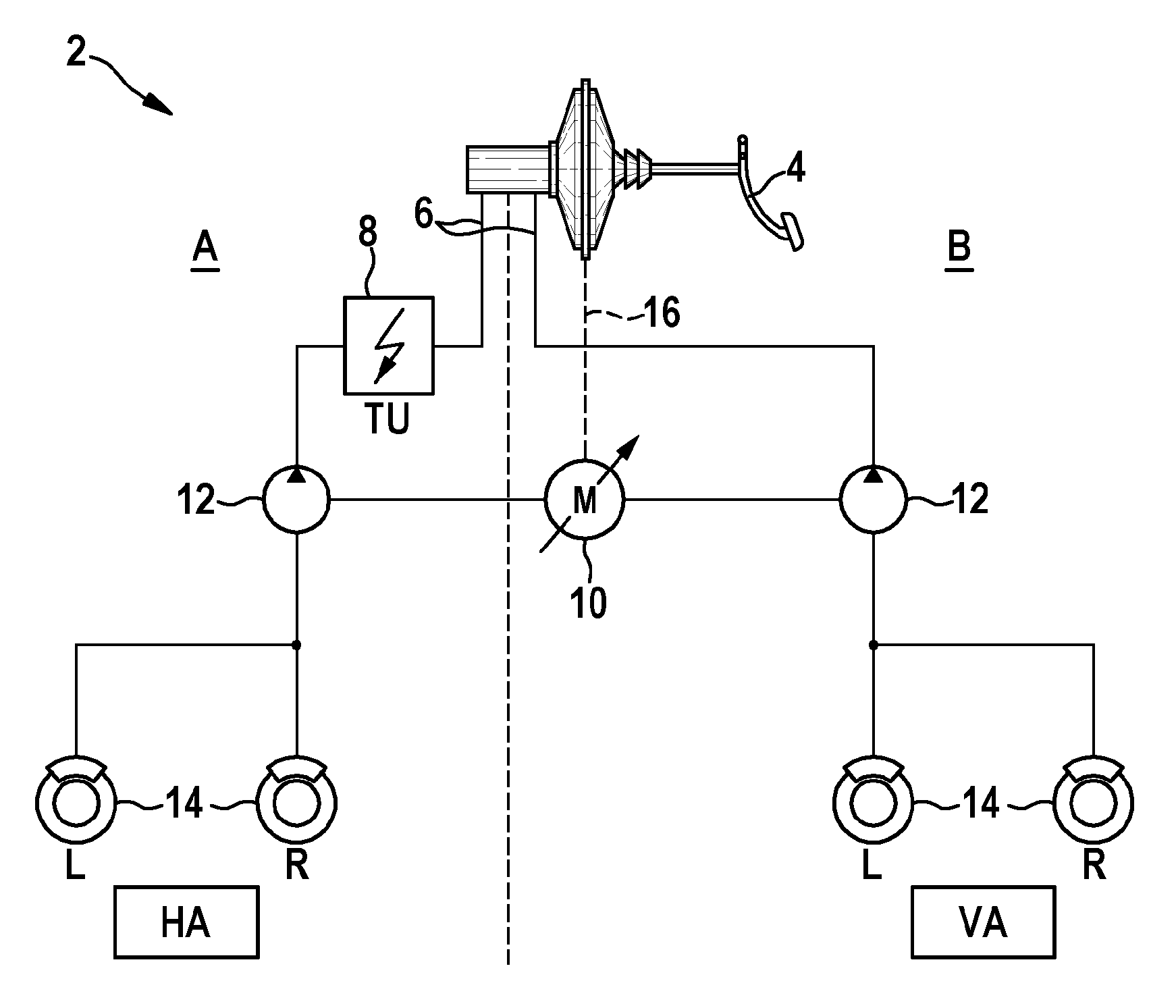
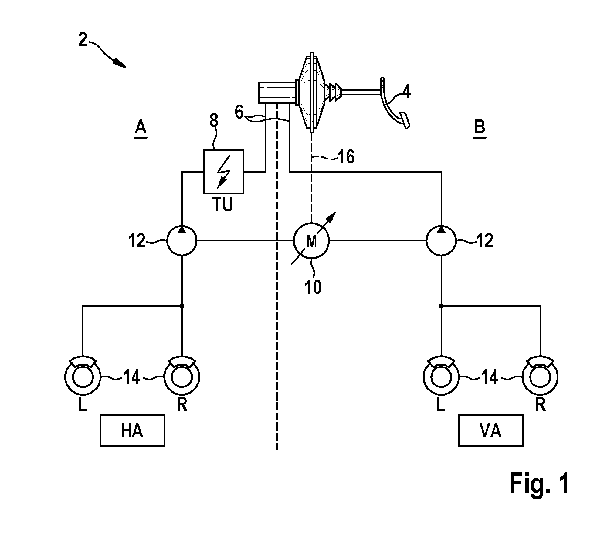
[0021]FIG. 1 shows a braking system 2 in highly simplified form, which is designed as a partial brake-by-wire system. On the one hand, a driver, by using brake pedal 4, may introduce a brake pressure into hydraulic line system 6, which finally leads to four wheels 14, for example, with use of suitably situated and guided hydraulic lines 6.

[0022]The hydraulic pressure acts on brake components (not shown in greater detail) on wheels 14, whereby braking of wheels 14 and therefore deceleration of the vehicle occurs. As an example, braking system 2 of FIG. 1 is divided into two brake-circuit partial circuits A and B, brake-circuit partial circuit A corresponding to the rear axle in the example while brake-circuit partial circuit B corresponds to the front axle of a two-axle vehicle in the example.

[0023]In addition, pump elements 12 are provide...


PUM


Abstract

A method for dimensioning a component of a braking system; the braking system having at least two brake-circuit partial circuits; each brake-circuit partial circuit having at least one pump element for building up a brake-circuit pressure and/or for returning brake-circuit fluid in an ABS case, the pump elements of the at least two brake-circuit partial circuits being operable using a motor element; and the at least two brake-circuit partial circuits being separable using a separating element, so that different brake-circuit pressures may be created in the at least two brake-circuit partial circuits.

Description

FIELD OF THE INVENTION[0001]The present invention relates to braking system technology. In particular, the present invention relates to braking systems having increased pressure buildup dynamics. Furthermore, the present invention relates in particular to a method for dimensioning a component of a braking system, a braking system for a vehicle, and a vehicle having a braking system according to the present invention.BACKGROUND INFORMATION[0002]Braking systems are used in vehicles to perform deceleration of a vehicle in a targeted and in particular moderate way during regular driving operation. In particularly extremal situations, for example, full braking, a braking system is frequently operated at its limit, to carry out the best possible or quickest possible braking of the vehicle, for example, to a standstill.[0003]One such scenario in which full braking may be necessary is pedestrian protection. It may thus occur, for example, due to inattention of the driver of a vehicle or als...

Claims


Application Information

Patent Timeline
Patent Type & Authority Applications(United States)
IPC IPC(8): B60T8/40B60T8/34B60T8/176
CPCB60T8/404B60T8/346B60T8/176B60T8/26B60T8/321B60T8/34B60T8/4013B60T13/66B60T17/02B60T8/4031B60T8/4072B60T8/50B60T2201/022B60T2270/82
Inventor BENZLER, STEFFENKUNZ, MICHAELSTRENGERT, STEFANDRUCKENMUELLER, HEIKO
Owner ROBERT BOSCH GMBH
Why Eureka
Try Eureka