Method of controlling injection pressure level in unit injectors

a technology of injection pressure level and injector, which is applied in the direction of electric control, machines/engines, mechanical equipment, etc., can solve the problems of inability to control the injection pressure level of peak injection pressure in an injection sequence, limited injection profile control, and inability to achieve the control of peak injection pressure sustained within the fuel injector, etc., to facilitate the return of the first portion

Inactive Publication Date: 2015-12-24
CATERPILLAR INC
View PDF4 Cites 12 Cited by
  • Summary
  • Abstract
  • Description
  • Claims
  • Application Information

AI Technical Summary

Benefits of technology

[0006]Various aspects of the present disclosure relate to a method to control an injection pressure level of fuel within a unit injector. The unit injector includes a first spill valve. The first spill valve is configured to allow return of a first portion of the fuel from the unit injector to a low-pressure fuel manifold. The method includes provision of a second spill valve in the unit injector, which is connected in parallel to the first spill valve. The second spill valve includes at least one of a controlled orifice or a fixed orifice. The fuel is delivered to the unit injector, with the first ...

Problems solved by technology

However, the inherent structure and function of the MEUI injectors make it difficult to control peak injection pressure levels in an injection sequence.
Therefore, there are limitations in the appropriate control of injection profiles of the fuel during an injection event...

Method used


Image

  • Method of controlling injection pressure level in unit injectors
  • Method of controlling injection pressure level in unit injectors
  • Method of controlling injection pressure level in unit injectors

Examples


Embodiment Construction

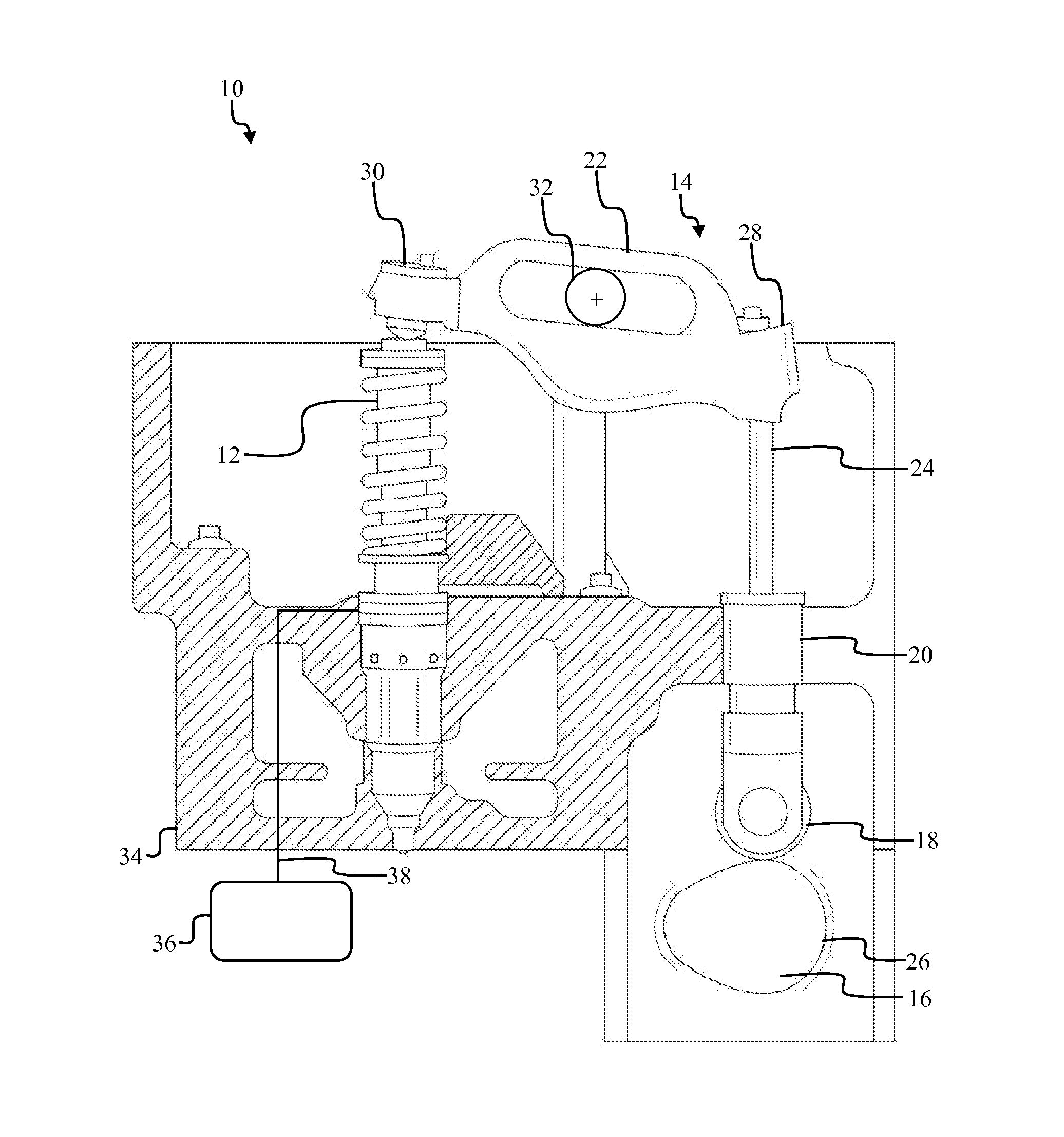
[0011]Referring to FIG. 1, there is shown an injector system 10 applied in an internal combustion engine (not shown). The injector system 10 includes a unit injector 12 and a cam arrangement 14. The unit injector 12 may embody a mechanically operated pump-type unit fuel injector. The unit injector 12 is driven by the cam arrangement 14, to selectively pressurize fuel within the unit injector 12 to a desired pressure level. The cam arrangement 14 includes a cam 16, a follower 18, a hydraulic lash adjuster 20, a rocker arm 22, and a push rod 24. The cam 16 includes a cam lobe 26, which acts as a driving surface. The cam 16 is operatively connected to a crankshaft (not shown), such that a rotation of the crankshaft (not shown) corresponds to the rotation of the cam 16. The cam 16 is in contact with the follower 18, such that the cam lobe 26 rotatably drives the follower 18, and subsequently results in a collective linear movement of the follower 18 and the push rod 24. The follower 18 ...


PUM


Abstract

A method to control an injection pressure level of fuel within a unit injector is provided. The method includes provision of a second spill valve in the unit injector, which is connected in parallel to a first spill valve. The fuel is delivered to the unit injector with the first spill valve maintained in a passive state. This facilitates return of the first portion of the fuel to the low-pressure fuel manifold. The first spill valve is actuated to an active state to block the flow of fuel to the low-pressure fuel manifold, to maintain the unit injector at the injection pressure level. The second spill valve is actuated concurrently or prior to the actuation of the first spill valve. This facilitates return of a second portion of the fuel to the low-pressure fuel manifold. This is done to limit the injection pressure level within the unit injector.

Description

TECHNICAL FIELD[0001]The present disclosure generally relates to a mechanical electronic unit injector. More particularly, the present disclosure relates to a method to control an injection pressure level in such a mechanical electronic unit injectors.BACKGROUND[0002]Mechanically actuated electronically controlled unit injectors (MEUI) have seen great success in compression ignition engines for many years. In recent years, MEUI injectors have acquired additional control capabilities via a spill valve actuated by a first solenoid and a nozzle check valve actuated by a second solenoid. MEUI fuel injectors may be actuated via rotation of a cam, which may be typically driven by a gear linkage to the crankshaft of an engine. The cam may rotate to move a plunger housed within the MEUI fuel injector, and the fuel may be initially displaced to a drain at low pressure for recirculation, via the spill valve. The spill valve may be closed to increase fuel pressure in the MEUI fuel injector. Fu...

Claims


Application Information

Patent Timeline
IPC IPC(8): F02D41/30F02M57/02F02M63/00F02M61/04
CPCF02D41/3005F02M63/0015F02M57/024F02M61/04
Inventor TANIS, DEREK A.HURLEY, CHRISTOPHER J.NIEMAN, DEREK E.VAIDYANATHAN, RAMAMURTHY
Owner CATERPILLAR INC
Why Eureka
Try Eureka