Electronic apparatus and method for measuring direction of output laser light

Active Publication Date: 2015-12-24
FUNAI ELECTRIC CO LTD
View PDF7 Cites 59 Cited by
  • Summary
  • Abstract
  • Description
  • Claims
  • Application Information

AI Technical Summary

Benefits of technology

[0026]Embodiments of the present invention cause the direction in which the laser light is o

Problems solved by technology

However, in the method described in Patent Literature 1, because a plurality o

Method used


Image

  • Electronic apparatus and method for measuring direction of output laser light
  • Electronic apparatus and method for measuring direction of output laser light
  • Electronic apparatus and method for measuring direction of output laser light

Examples


Example

[0045]Embodiments according to the present invention will be described in detail below using the drawings. Each drawing does not necessarily strictly illustrate each dimension, each dimension ratio, and the like.

[0046]Numerical values, shapes, materials, components, disposition positions and connection modes of the components, steps, orders of the steps, and the like illustrated in the one or more embodiments of the present invention below are but examples and are not intended to limit the present invention.

An Example

[0047]A laser range finder of one or more embodiments of an example will be described based on FIGS. 1 to 17.

(1. Configuration of Laser Range Finder According to One or More Embodiments)

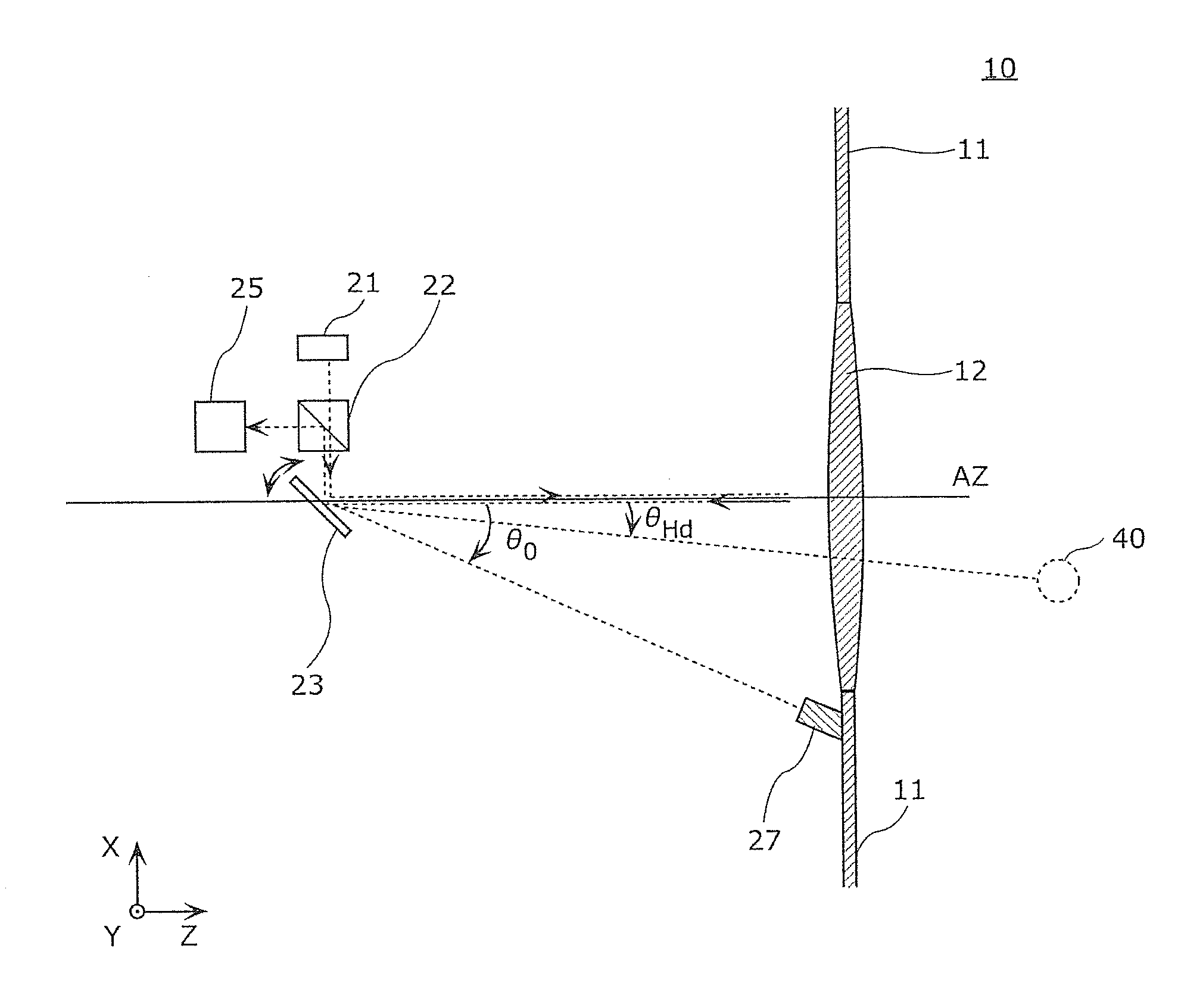
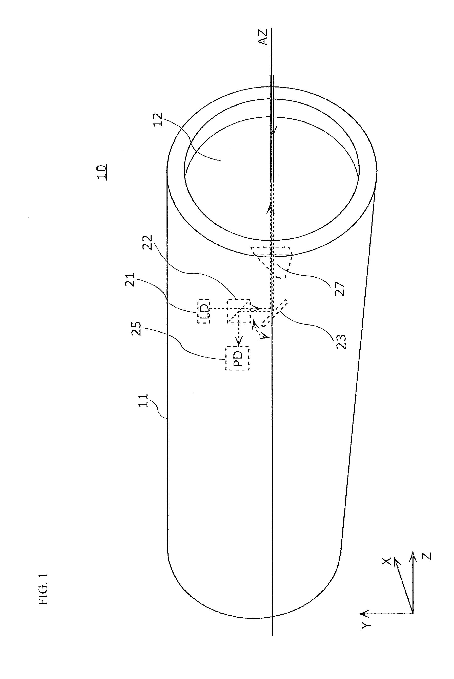
[0048]FIG. 1 is a perspective view illustrating a configuration of a laser range finder 10 according to one or more embodiments of the example of the present invention. In FIG. 1, the z-axis is an axis parallel to an axis AZ of the laser range finder (reference direction) and the x-axis ...


PUM


Abstract

An electronic apparatus includes a light source that outputs a laser light; a scanning unit that scans the laser light; a reflective member having a reflective surface that reflects the laser light; a light-receiving unit that receives a first reflected light reflected by the reflective member; and a signal processing unit that calculates a distance from the light source to the reflective surface using the first reflected light and determines a direction in which the laser light is output using the distance.

Description

TECHNICAL FIELD [0001]The present invention relates generally to an electronic apparatus (e.g., a laser range finder).BACKGROUND [0002]As a sensor for sensing an obstacle when a robot is autonomously moving or a sensor for sensing a person, there is, for example, a laser range finder (LRF).[0003]Conventional laser range finders perform measurement of a time from when a laser light is output to when a reflected light, which is the laser light striking an object and being reflected, returns and calculates a distance to the object from a measurement result. The laser range finders, by changing a direction in which the laser light is output in a horizontal direction and a vertical direction, perform measurement of the distance to the object in an entirety of a range where measurement of the distance is performed (referred to hereinbelow as “scanning range”).[0004]The conventional laser range finders comprise, for example, a laser diode (LD) that outputs the laser light, a mirror that ad...

Claims


Application Information

Patent Timeline
IPC IPC(8): G01S17/42G01S7/481
CPCG01S7/4817G01S17/42G01S7/4972G02B26/127G02B26/0833G02B26/101
Inventor SETONO, SHINGOHORIBE, RYUSUKEMURAYAMA, MANABUMASUDA, YUICHIROHIRAI, TOMOHISAMUSHIMOTO, ATSUSHI
Owner FUNAI ELECTRIC CO LTD
Why Eureka
Try Eureka