
Eureka
For R&D, Eureka makes reading and utilizing patents & technical documents easy.
Eureka AIR
Designed for self-driven R&D workflows. Generate viable solutions, solve complex R&D challenges, empower your innovation with AI.

Eureka Materials
Designed for material experts only. Revolutionize your material R&D, from search, analyze, to developing new materials.

TechResearch
Generate reliable direction feasibility study reports for your R&D in just a few steps.

TechSeek
Discover and master advanced knowledge NOW. Basics, ideas, possibilities, all at once.

TechMind
As an expert in R&D Theories, TechMind can generates customized viable solutions instantly.

TechRisk
Analyze your overall solution with one click, know your potential R&D risks in advance.

TechMonitor
Get weekly tech updates, stay abreast of the latest tech innovations and key insights.
Projection device and projection system
- Summary
- Abstract
- Description
- Claims
- Application Information
AI Technical Summary
Benefits of technology
Problems solved by technology
Method used
Image

Examples
first example
[0092]Next, the first example of the present invention will be described in detail with reference to FIG. 3.
[0093]The reference signs in the first example and a later-described second example are defined as follows.
[0094]f: focal length in entire system
[0095]NA: numerical aperture
[0096]ω: half field angle (deg)
[0097]R: curvature radius (paraxial curvature radius on the aspheric surface)
[0098]D: surface distance
[0099]Nd: refractive index
[0100]vd: Abbe number
[0101]K: conic constant of aspheric surface
[0102]Ai: i-th aspheric surface coefficient
[0103]Cj: free-form surface coefficient
[0104]The shape of the aspheric surface is expressed by a following known expression (5) by setting X as an amount of the aspheric surface in an optical axis direction, defining an inverse of paraxial curvature radius (paraxial curvature) as C, a height from the optical axis as H, and a conic constant as K, and using the above-mentioned aspheric surface coefficient of each degree.
[Expression5]X=C·H21+{1-(1+K...
second embodiment
FIRST EXAMPLE
[0208]Next, a configuration of a projection optical system of a projection device according to the above-described embodiment of the present invention will be described in detail.
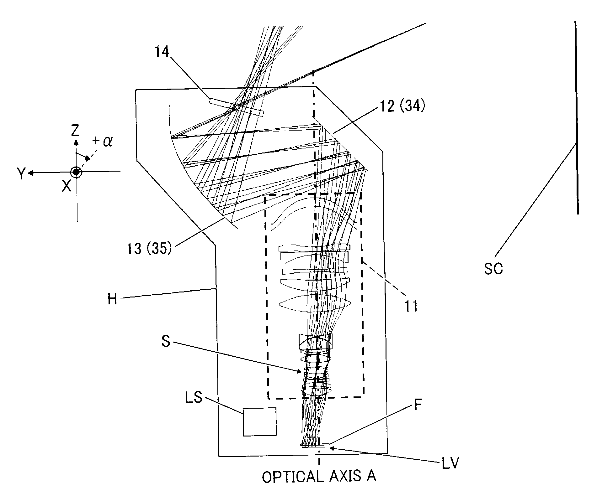
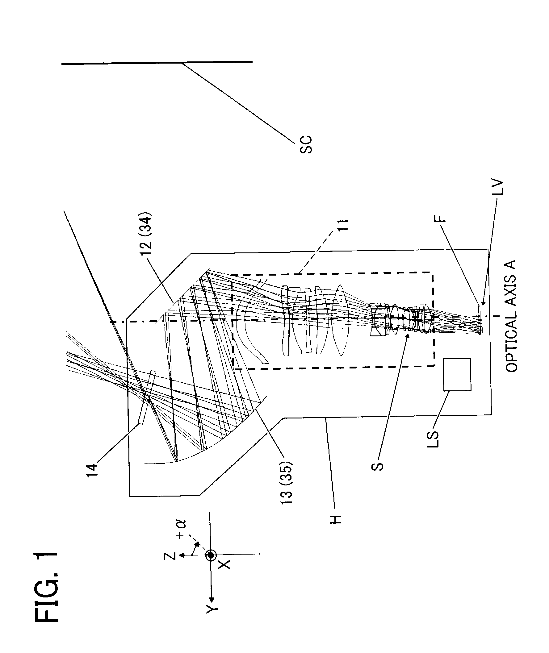
[0209]FIG. 13 is a cross-sectional view illustrating the configuration of the projection device together with an optical path according to a first example of the second embodiment of the present invention.
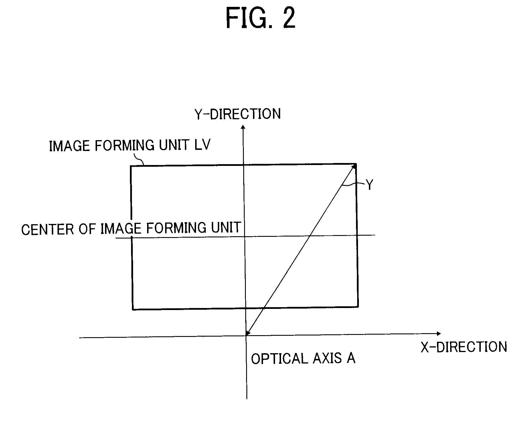
[0210]FIG. 14 is an explanatory diagram illustrating a positional relation between an optical axis and a center of an image forming unit in which an image is formed, when the image forming unit is shifted in Y-direction by a predetermined amount relative to the optical axis.
[0211]FIG. 15 (FIG. 15A and FIG. 15B) is a cross-sectional view illustrating moving positions of a focusing lens for each projection size of the projection optical system used in the projection device according to the first example of the second embodiment of the present invention, and FIG. 15A illustrates a case where the...
second example
[0294]FIG. 24 is a cross-sectional view illustrating a configuration of a projection device together with an optical path according to a second example of the second embodiment of the present invention.
[0295]FIG. 25 (FIGS. 25A and 25B) is a cross-sectional view illustrating moving positions of a focusing lens for each projection size of the projection optical system used in the projection device according to the second example of the second embodiment of the present invention, and FIG. 25A illustrates a case where the projection size is a long distance side (100 inches), and FIG. 25B illustrates a case where the projection size is a short distance side (80 inches).
[0296]In FIG. 24, a reference sign LV indicates an image forming unit. The image forming unit LV is, more specifically, a light valve such as a “Digital Micro-mirror Device (abbreviated as DMD)”, a “transmissive liquid crystal panel”, and a “reflective liquid crystal panel”, and a portion indicated by the reference sign LV...
PUM
 Abstract
Description
Claims
Application Information
 - R&D Engineer
- R&D Manager
- IP Professional
- Industry Leading Data Capabilities
- Powerful AI technology
- Patent DNA Extraction
Browse by: Latest US Patents, China's latest patents, Technical Efficacy Thesaurus, Application Domain, Technology Topic, Popular Technical Reports.
© 2024 PatSnap. All rights reserved.Legal|Privacy policy|Modern Slavery Act Transparency Statement|Sitemap|About US| Contact US: help@patsnap.com