
Method and apparatus for treating logging cable

a technology of electromechanical cable and logging method, which is applied in the direction of cables, insulated conductors, furnaces, etc., can solve the problems of difficult to calculate permanent stretch characteristics, adversely affect the precision use of cables, and inability to accurately logging newly manufactured electromechanical cables, etc., to achieve the effect of cooling and hardening of electromechanical cables more rapidly

Inactive Publication Date: 2015-12-24
LEGGETT HENRY H
View PDF6 Cites 12 Cited by
  • Summary
  • Abstract
  • Description
  • Claims
  • Application Information

AI Technical Summary

Benefits of technology

The present invention provides a method and apparatus for applying controlled stretching and working to a newly manufactured electromechanical cable to remove or dissipate the cable's permanent stretch characteristics for accurate well logging activities. A powered or driven capstan and a braking capstan with a spiral groove are used to prevent slippage of the cable during processing. The solution involves heating the cable, stretching it, and allowing it to cool to ambient temperature before re-tightening its outer armor. The heated cable can be moved through a cooler device to accelerate the cooling and hardening process.

Problems solved by technology

Newly manufactured electromechanical cable typically has elastic stretch characteristics which can be easily calculated, but also has permanent stretch characteristics which are quite difficult to calculate.
Each time the electromechanical cable is run down-hole for logging or other well service activities the permanent stretch characteristics change to some extent and adversely affect precision use of the cable, especially for well logging.
Consequently, newly manufactured electromechanical cable is not acceptable for accurate well logging since it is difficult to precisely confirm the location of a logging tool within a well.
Obviously, running and retrieving an electromechanical cable multiple times while doing no income producing work is a time consuming and expensive proposition.

Method used


Image

  • Method and apparatus for treating logging cable
  • Method and apparatus for treating logging cable
  • Method and apparatus for treating logging cable

Examples


Embodiment Construction

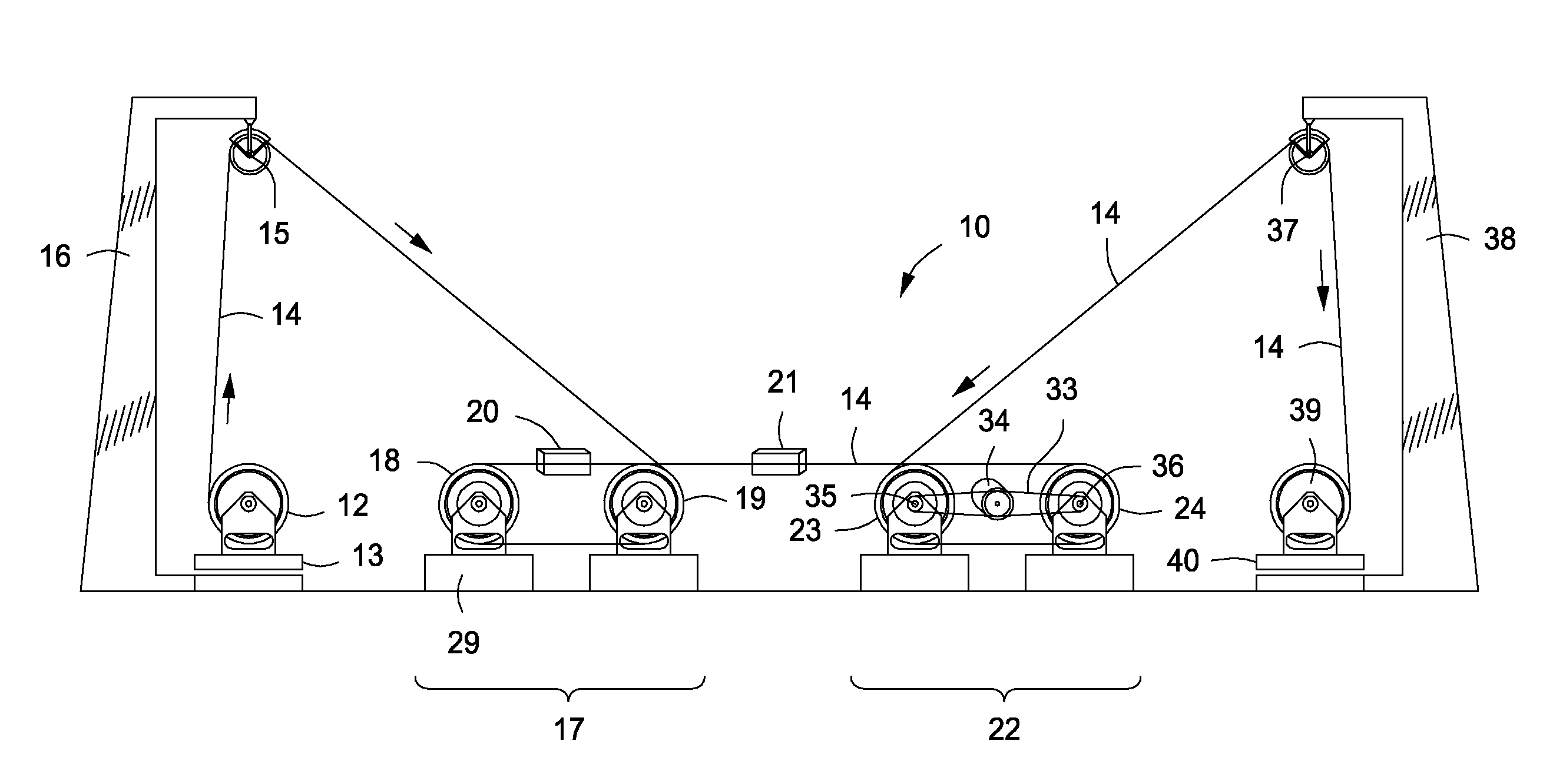
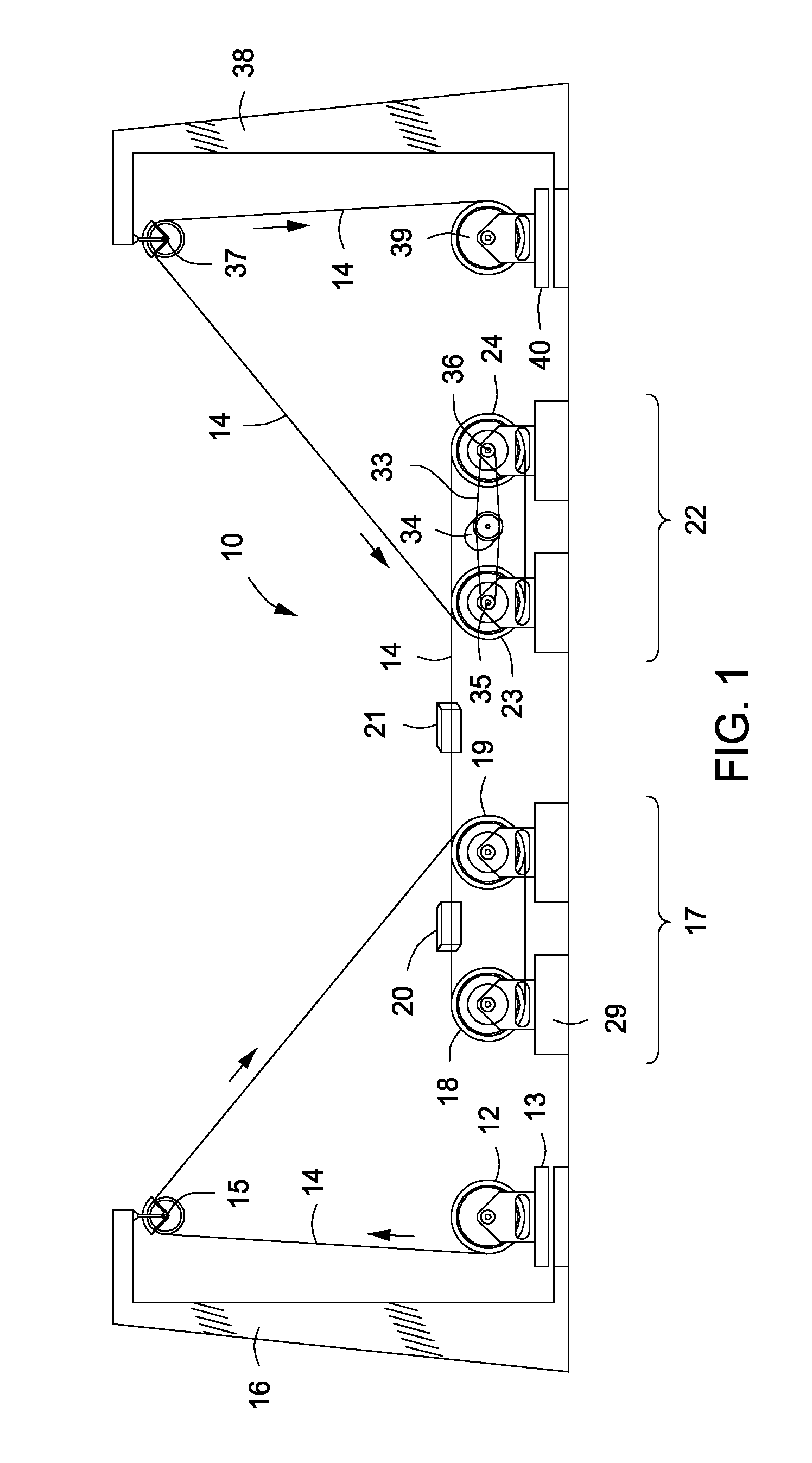
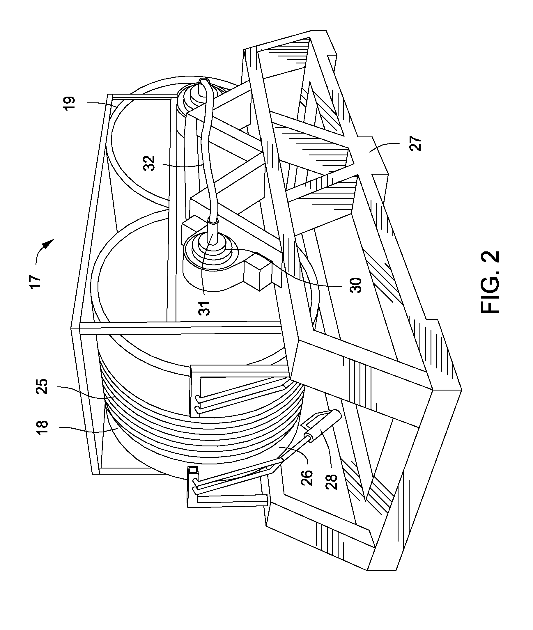
[0023]Referring now to the drawings and first to FIG. 1, a schematic illustration of an electromechanical cable processing system, shown generally at 10, includes a rotary supply reel or drum 12 that is mounted on a turntable 13 containing a length, for example 25,000 feet or more, of a particular type of newly manufactured electromechanical cable 14. The electromechanical cable is withdrawn from the cable supply or let-off drum 12 and is directed upwardly and over a sheave 15 while the cable loosening turntable is rotated in a direction for loosening the outer spiral wound armor of the cable and consequently tightening the oppositely wound inner armor. As will be described in greater detail below when the finished cable is taken up it is rotated in the opposite direction by a similar turntable, thereby tightening the spiral wound outer armor substantially to its original condition of tightness and loosening the inner armor substantially to its original condition of tightness. This ...


PUM

PropertyMeasurementUnit
depthaaaaaaaaaa
tensionaaaaaaaaaa
lengthaaaaaaaaaa

Abstract

A method and apparatus for removing permanent stretch characteristics of electromechanical cable by application of predetermined tension and heat to the cable while continuously moving the cable linearly from a supply drum, through spaced capstans and to a take-up drum. A cable heater is positioned at a braking capstan to soften the polymer insulation of the electrical conductor or conductors and permit tension responsive conductor movement relative to the polymer insulation, thus dissipating the permanent stretch and rendering the cable suitable for accurate well logging and for conducting other downhole well services. The outer cable armor is loosened to start the seasoning process and is tightened as it is taken up at completion of the process.

Description

BACKGROUND OF THE INVENTION[0001]1. Field of the Invention[0002]The present invention relates generally to the use of electromechanical cable, typically logging cable, in the treatment of wells for enhanced production of petroleum products, such as crude oil, natural gas, distillate and other petroleum constituents. More particularly, the present invention concerns the use of logging cable to accomplish precision location within wells of the various well tools that are employed for well servicing activities. Even more specifically, the present invention concerns one or more processes that are employed to prepare an electromechanical logging cable so that its permanent stretch characteristic is substantially eliminated and permitting a well tool connected with the logging cable to be more precisely located within a well simply by calculating the elastic stretch of the cable.[0003]2. Description of the Prior Art[0004]It is well known in the well drilling and completion industry that w...

Claims


Application Information

Patent Timeline
Patent Type & Authority Applications(United States)
IPC IPC(8): H01B13/00B23P6/00H01B7/04B65H59/16B65H59/18D02G1/02B21D1/06
CPCH01B13/0036D02G1/02B23P6/00H01B7/046B65H59/16B65H59/18B21D1/06B65H49/32B65H51/12B65H51/20B65H54/12B65H59/388B65H2701/34
Inventor LEGGETT, HENRY H.
Owner LEGGETT HENRY H
Learn More