Non-burning type flavor inhaler
a flavor inhaler and non-burning technology, which is applied in tobacco treatment, food science, tobacco, etc., can solve the problems of loss of flavor, bad smell of latent heat storage materials such as sodium acetate, etc., and achieve the effect of improving flavor without losing flavor, high latent heat, and high temperatur
- Summary
- Abstract
- Description
- Claims
- Application Information
AI Technical Summary
Benefits of technology
Problems solved by technology
Method used
Image
Examples
first embodiment
(Non-Burning Type Flavor Inhaler)
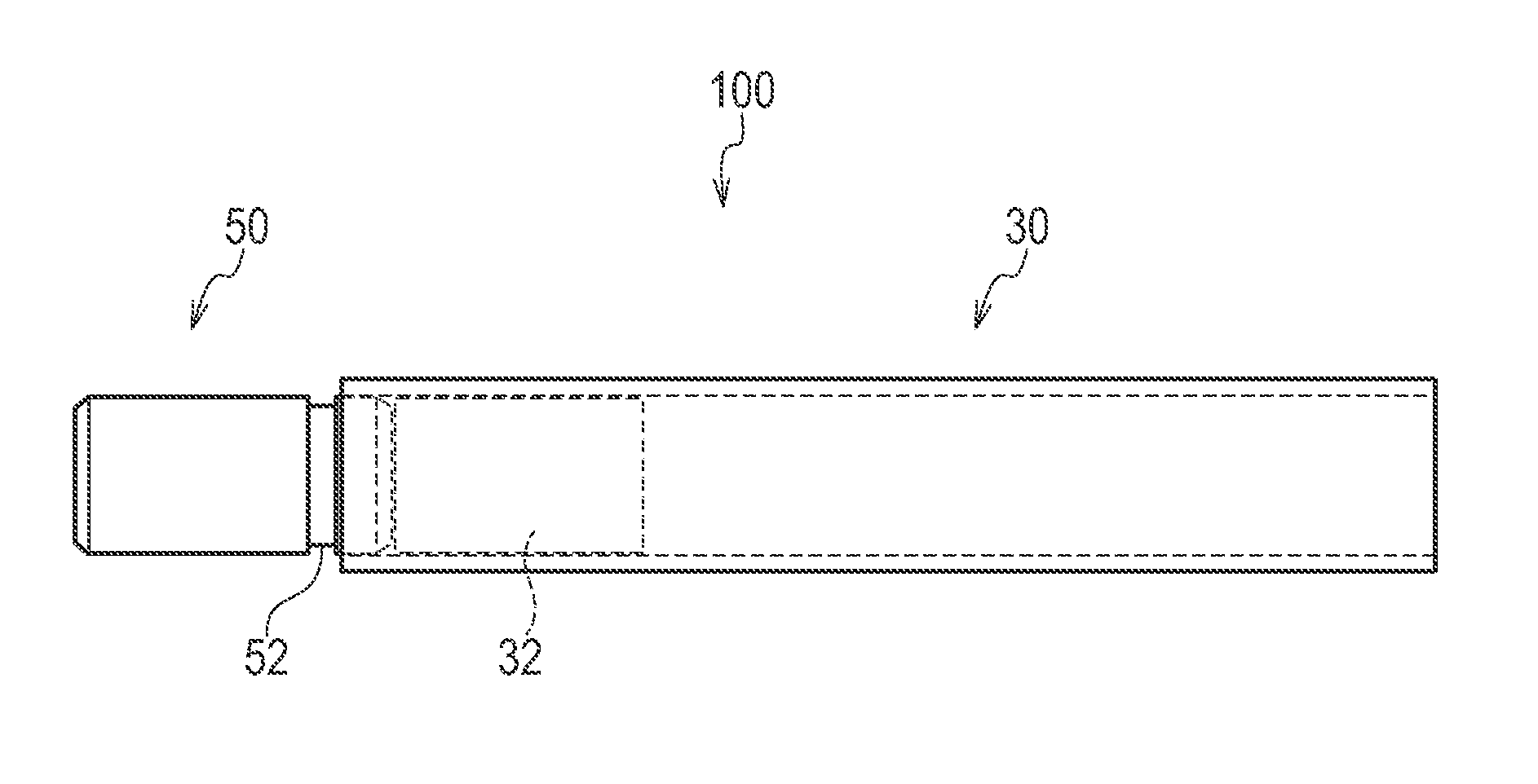
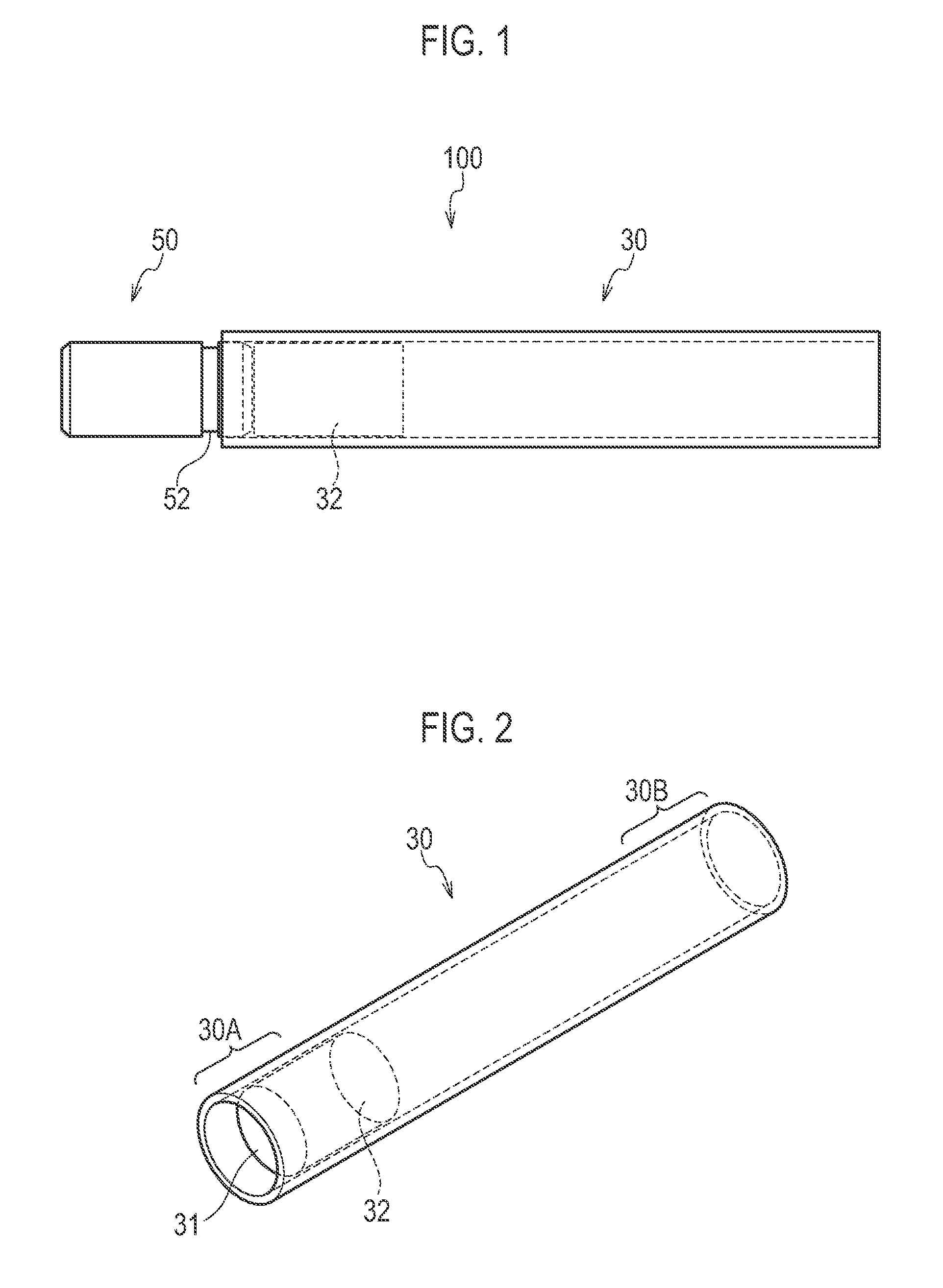
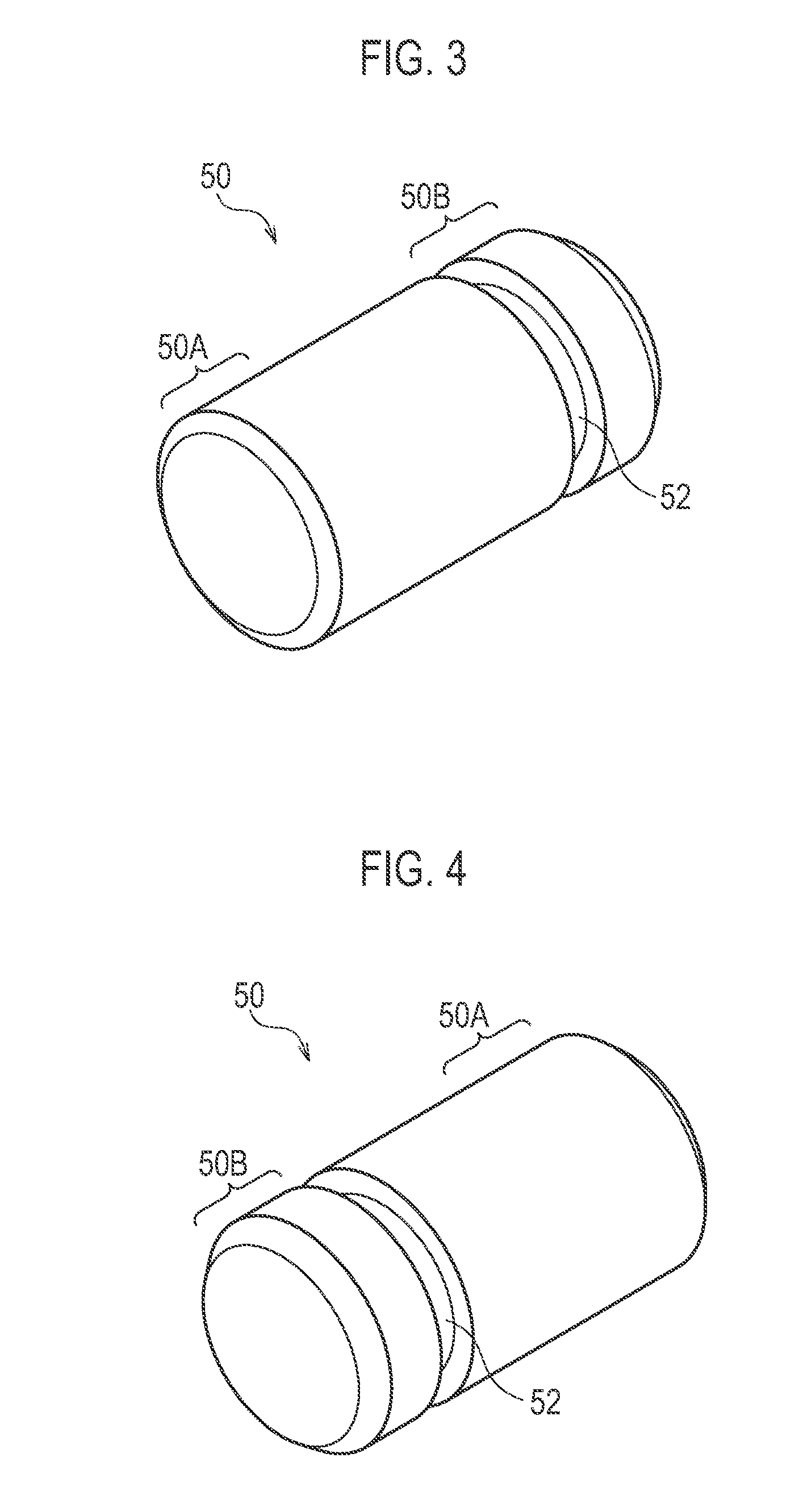
[0043]Hereinafter, a non-burning type flavor inhaler according to a first embodiment will be described. FIG. 1 is a drawing showing a non-burning type flavor inhaler 100 according to the first embodiment. FIG. 2 is a drawing showing a holding member 30. FIG. 3 and FIG. 4 are drawings showing a heat source 50. FIG. 3 is a drawing showing the heat source 50 as seen from the side of the non-insertion end 50A. FIG. 4 is a drawing showing the heat source 50 as seen from the side of the insertion end 50B.
[0044]As shown in FIG. 1, the non-burning type flavor inhaler 100 has a holding member 30 and a heat source 50. In the first embodiment, it must be noted that the non-burning type flavor inhaler 100 is a flavor inhaler that does not burn.
[0045]As shown in FIG. 2, the holding member 30 detachably holds the heat source 50. The holding member 30 has a supporting end 30A and a mouthpiece-side end 30B. The supporting end 30A is an end that holds the heat source...
first modification
[First Modification]
[0099]Hereinafter, a first modification of the first embodiment will be described. Mainly differences from the first embodiment are described below.
[0100]In the first modification, as shown in FIG. 11, the holding member 30 has a side hole 30H that leads to the cavity 31. The side hole 30H extends from the support end 30A along a direction that crosses the direction facing the mouthpiece-side end 30B. The side hole 30H is preferably provided on the support end 30A, and adjoining the flavor source 32.
[0101]Moreover, in addition to the flavor source 32, the holding member 30 has a rectification member 33. The flavor source 32, for example, may be realized by laminating a member having air permeability, such as a nonwoven cloth and granular tobacco leaves to form the flavor source 32 in the shape of a sheet through thermal fusion bonding, which is then arranged in a disk shape (thin columnar shape). The rectification member 33 is provided at the side of the mouthpie...
second modification
[Second Modification]
[0103]Hereinafter, a second modification of the first embodiment will be described. Mainly differences from the first embodiment are described below.
[0104]In the second modification, as shown in FIG. 13, the holding member 30 has a side hole 30H that leads to the cavity 31. The configuration of the side hole 30H is the same as in the first modification.
[0105]In the second modification, the flavor source 32 may be realized by laminating a member having air permeability, such as a nonwoven cloth and granular tobacco leaves to form the flavor source 32 in the shape of a sheet through thermal fusion bonding, which is then arranged in a cylindrical shape having an opening in the center for inserting the heat source 50. Moreover, the flavor source 32 may be a cylindrical body formed through extrusion that has an opening in the axial direction and air permeability inside.
[0106]When a user inhales the flavor, the air that is taken in from the side hole 3011 is led to th...
PUM
 Abstract
Description
Claims
Application Information
 - R&D
- Intellectual Property
- Life Sciences
- Materials
- Tech Scout
- Unparalleled Data Quality
- Higher Quality Content
- 60% Fewer Hallucinations
Browse by: Latest US Patents, China's latest patents, Technical Efficacy Thesaurus, Application Domain, Technology Topic, Popular Technical Reports.
© 2025 PatSnap. All rights reserved.Legal|Privacy policy|Modern Slavery Act Transparency Statement|Sitemap|About US| Contact US: help@patsnap.com


