Radiation sensor device and fluid treatment system containing same

a technology of radiation sensor and fluid treatment system, which is applied in the direction of photometry, lighting and heating apparatus, water/sludge/sewage treatment, etc., can solve the problems of additional hydraulic head loss, difficult mounting of sensors to monitor lamp output, and creating a “catch” for fouling materials, etc., to minimize or prevent thermal build-up

Inactive Publication Date: 2006-01-12
TROJAN TECH
View PDF9 Cites 8 Cited by
  • Summary
  • Abstract
  • Description
  • Claims
  • Application Information

AI Technical Summary

Benefits of technology

[0039] In another embodiment, radiation specific opacity may be conferred to the protective sleeve by placement in the interior or the exterior thereof a filter layer which will exclude deleterious radiation but allow radiation of interest to pass through the protective sleeve to be detected by the sensor. Thus, again using the example of an ultraviolet radiation sensor, in many cases, the wavelength of interest for detection is in the range of from about 210 to about 300 nm. It is possible to utilize a layer made from a filter material which will allow substantially only radiation in this range through the protec

Problems solved by technology

Such an arrangement poses difficulties for mounting sensors to monitor lamp output.
The surrounding structure is usually a pressurized vessel or other construction not well suited for insertion of instrumentation.
Further, since the optical radiation sensor is disposed within an existing element (the protective sleeve) of the radiation source module, incorporation of the sensor in the module does not result in any additional hydraulic head loss and/or does not create a “catch” for fouling materials.
When such a high intensity radiation field is used to treat water having relatively high transmittance, the sensor assembly (or assemblies) used in the fluid treatment system are susceptible to overheating

Method used


Image

  • Radiation sensor device and fluid treatment system containing same
  • Radiation sensor device and fluid treatment system containing same
  • Radiation sensor device and fluid treatment system containing same

Examples


Embodiment Construction

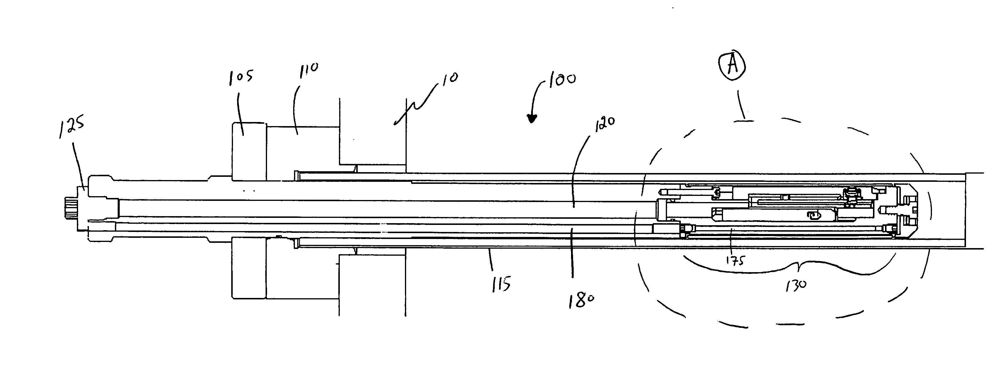
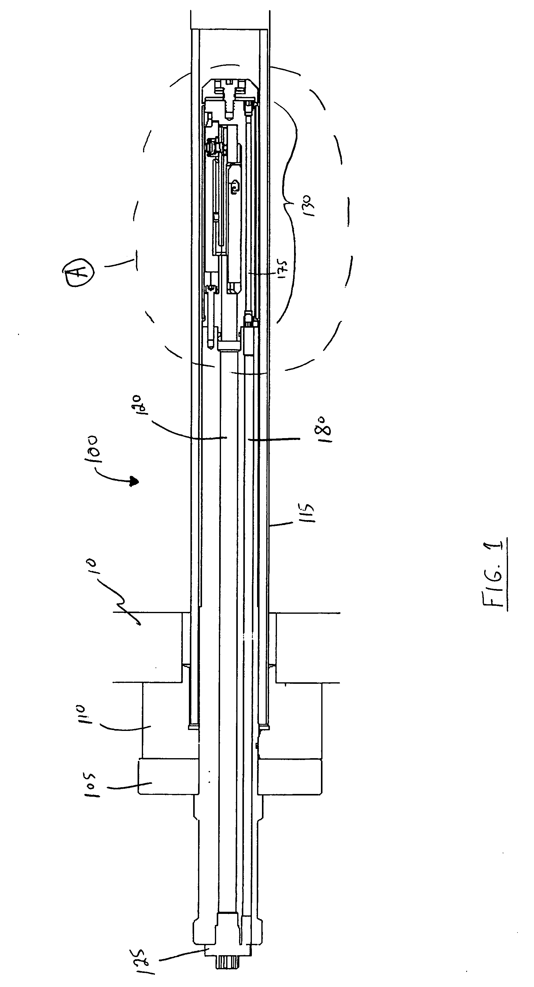
[0045] With reference to FIGS. 1 and 2, there is illustrated a radiation sensor device 100. Radiation sensor device 100 is secured to a wall 10 of a reactor such as one described hereinabove. The precise manner in which radiation sensor device 100 may be affixed to wall 10 is not particularly restricted. For example, this can be done through the use of an appropriate combination of mechanical securing elements and O-rings or the like.

[0046] Radiation sensor device 100 comprises a gland plate 105 and a transition gland plate 110 both positioned on the exterior of the reactor defined by wall 10.

[0047] Radiation sensor device 100 further comprises a protective sleeve 115 which is substantially radiation transparent. Disposed within protective sleeve 115 is a support element 120.

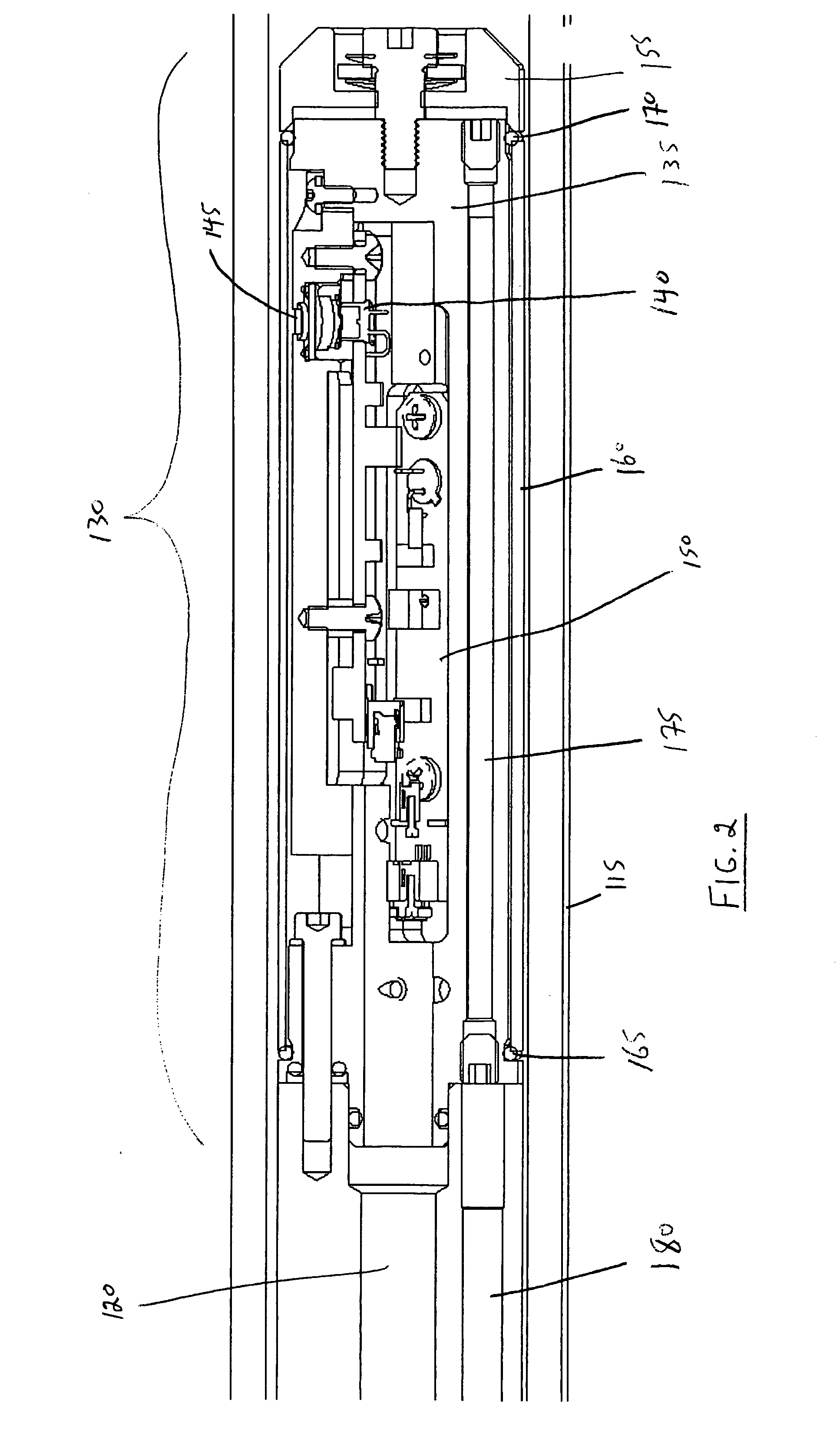
[0048] Disposed at a proximal end of support element 120 is an electrical connector 125. Disposed at a distal end of support element 120 is a radiation sensor apparatus 130 which will be described in more det...


PUM


Abstract

The invention relates to a radiation sensor device comprising a housing, a radiation sensor secured with respect to a first portion of the housing and a heat pipe in thermal communication with the first portion of the housing, the heat pipe being configured to transfer heat from portion of the house to a second portion of the housing remote from the first portion of the housing. The heat pipe may be used advantageously to transport or transfer heat away from the sensor components of the device to an area remote therefrom. The heat pipe can be used to transfer heat at a rate that is thousands of times higher than copper. The radiation sensor device may be used in an ultraviolet radiation fluid treatment system such as an ultraviolet radiation water disinfection system.

Description

CROSS-REFERENCE TO RELATED APPLICATION [0001] The present application claims the benefit under 35 U.S.C. §119(e) of provisional patent application Ser. No. 60 / 583,613, filed Jun. 30, 2005, the contents of which are hereby incorporated by reference.BACKGROUND OF THE INVENTION [0002] 1. Field of the Invention [0003] In one of its aspects, the present invention relates to a radiation sensor device. In another of its aspects, the present invention relates to a fluid treatment system comprising a novel radiation sensor device. [0004] 2. Description of the Prior Art [0005] Optical radiation sensors are known and find widespread use in a number of applications. One of the principal applications of optical radiation sensors is in the field of ultraviolet radiation fluid disinfection systems. [0006] It is known that the irradiation of water with ultraviolet light will disinfect the water by inactivation of microorganisms in the water, provided the irradiance and exposure duration are above a...

Claims


Application Information

Patent Timeline
IPC IPC(8): G01J1/42
CPCA61L2/08G01N2201/127A61L2/085A61L2/10C02F1/325C02F2201/326F28D15/0275G01J1/02G01J1/0204G01J1/0252G01J1/0271G01J1/429G01J2001/028G01N21/274A61L2/084
Inventor FRASER, JIMDRAGOI, CATALINAGERARDI, JENNIFERMOLYNEUX, TANYA
Owner TROJAN TECH
Why Eureka
Try Eureka