Chemical reactor with heat pipe cooling

a technology of chemical reactors and heat pipes, applied in indirect heat exchangers, lighting and heating apparatuses, transportation and packaging, etc., can solve the problems of limited convection heat transfer and evaporative cooling, and achieve the effect of prolonging service life and low maintenance cos

Inactive Publication Date: 2005-11-17
SAUDI BASIC IND CORP SA
View PDF12 Cites 8 Cited by
  • Summary
  • Abstract
  • Description
  • Claims
  • Application Information

AI Technical Summary

Benefits of technology

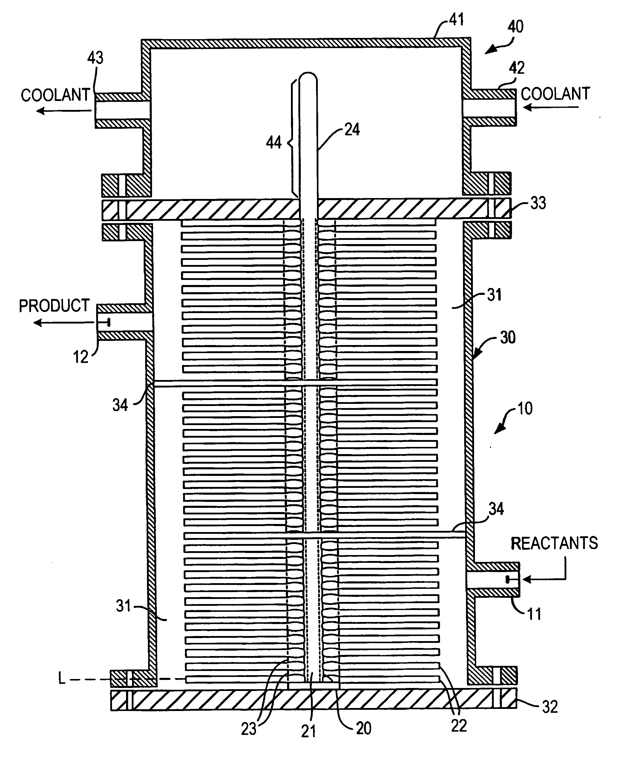
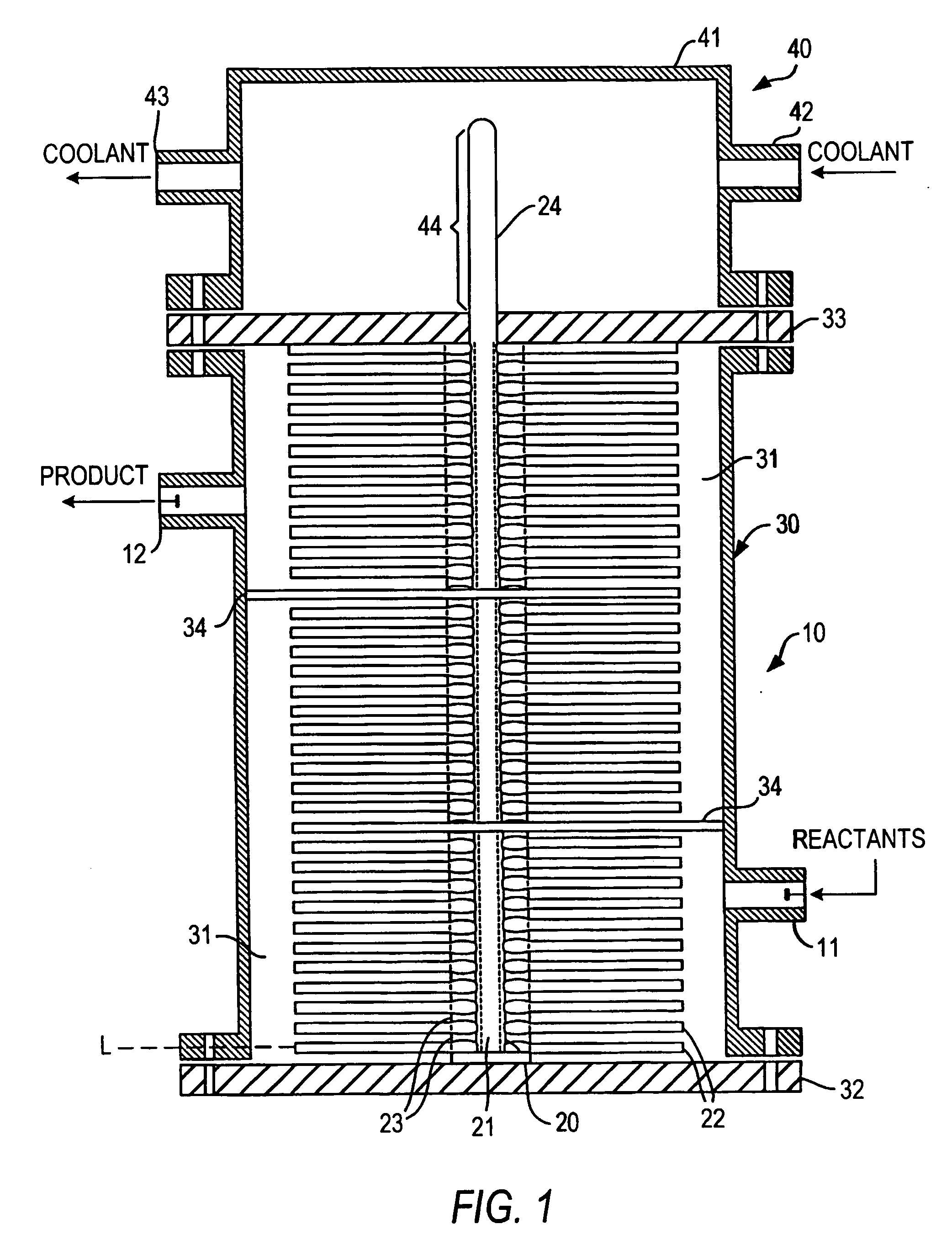
[0018] Because the evaporation of a pure heat transfer fluid occurs at a single temperature and the heat transfer coefficients for the heat pipe heat transfer system of the present invention are very good, a stratified flow reactor equipped with a heat pipe heat exchange device according to the present invention can be operated at essentially isothermal conditions.
[0023] When a reaction mixture is viscous such as a polymer syrup, heat transfer through the reactor of the invention is superior to convection, direct evaporation or conduction. The invention utilizes all three of these methods of heat transfer with maximum effectiveness without causing detrimental side effects. Heat of reaction is evenly extracted from the reacting viscous polymer syrup as it flows, in a laminar fashion, past the plurality of fins in the reactor shell. The fins can be made of a multitude of geometric shapes and materials of construction. Using conductive metals such as copper and aluminum alloys enhances thermal performance when these the materials are compatible with the process fluid. Conductance is further increased by constructing flat heat pipes as fins or embedding mini heat pipes within conventional fins. Conductance over long distance is avoided by locating the fins a short distance from the heat pipe or heat pipes. The heat pipe or pipes of the reactor act as collecting header(s) where the heat of reaction is transferred very quickly through indirect evaporation. No evaporation of monomers is involved. The use of a suitable internal fluid with a high latent heat of evaporation, such as water, can even improve heat transfer over the direct evaporation of the monomers themselves.
[0026] If a heat pipe in the reactor fails, the reactor is minimally affected as small and temporary contamination with the heat transfer fluid does not require a plant outage and heat load is taken over by other heat pipes in the vicinity of the failed heat pipe. The improved reliability means extended service life and low maintenance cost.
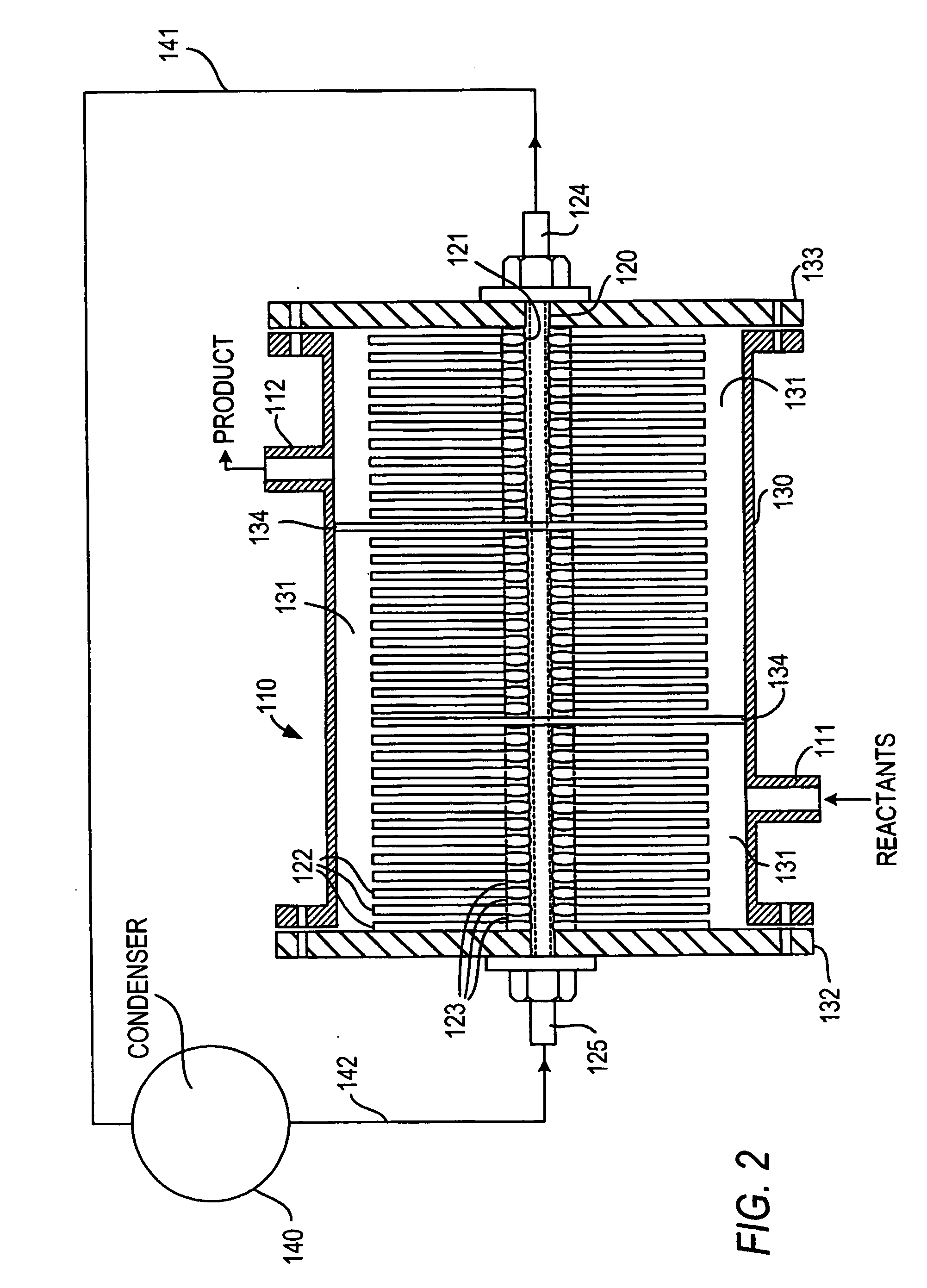
[0027] In the thermosyphon heat pipe embodiment of the invention, gravity or a pump is used to return reactor heat transfer fluid condensate to the reactor heat pipe(s) through separate piping. In a variant of this embodiment, the heat pipe(s) can communicate with a low-pressure vapor (steam) header serving a network of vapor (steam) users. In such case, a source of clean heat transfer fluid, such as boiler feed water, is required. The advantages of using thermosyphon heat pipe(s) in the reactor of the invention over sealed heat pipes include: 1) the cogeneration of low-pressure steam from reactor waste heat and elimination of reactor coolers, and 2) enabling the remote location of condensers with more surface area and multiple forms of cooling.
[0032] The reactor of the invention can be operated hydraulically full, meaning without vapor space. In this way, for any given flow rate of reactants the residence time in the reactor is known. This flow scheme simplifies process control enormously. A pump is used to push the material through the reactor or a series of reactors. Flow measurement can be made simply and accurately at the beginning of the process when viscosity is low, and there is no need to control the level or net weight of the reaction vessel, as is required with partially full reactors. Simplified instrumentation and control translates into very predictable and consistent polymer properties and ease of operation.

Problems solved by technology

Convection heat transfer is limited by many factors, including the velocity of the heat transfer fluid, the temperature differential between the reaction mixture and the cooling fluid, the viscosity of the heat transfer fluids, the surface area available for heat transfer, the materials of construction of the heat transfer device and the condition of the heat transfer surfaces, i.e., whether they are fouled.
Conventional evaporative cooling from a submerged heat transfer surface enjoys higher heat transfer coefficients than convection cooling, but is limited by the liquid phase surrounding the submerged tubes.

Method used


Image

  • Chemical reactor with heat pipe cooling
  • Chemical reactor with heat pipe cooling
  • Chemical reactor with heat pipe cooling

Examples


example

[0066] The following example illustrates the efficacy of the reactors of the invention to maintain essentially isothermal conditions in chemicals and especially polymerization reactions.

[0067] Polystyrene mass polymerization technologies are differentiated by the configuration of the main polymerization reactors used to bring conversion from 30% to 45% solids to 65% to 85% solids. During the course of the polymerization reaction large amounts of heat is evolved. If this heat of reaction is not removed, the reactor temperature will increase causing an unwanted and uncontrolled spread of the polymer molecular weight which adversely affects polymer properties.

[0068] A polystyrene mass polymerization is conducted in a reactor according to the invention consisting of a jacketed vertical pipe containing several straight heat pipes onto which are fitted a number of fins. The inside of the heat pipes is covered with a porous medium from which a heat transfer fluid is vaporized to provide ...


PUM


Abstract

A polymerization reactor (10) for exothermic liquid phase reactions comprises a reaction zone (31) which is divided into a plurality of channels by thermally conductive heat transfer fins (22) which are conductively mounted on one or more heat pipes (20) for the removal of heat of reaction from reactants and reaction products flowing between the heat transfer fins. The reactor (10) of the invention is capable of maintaining essentially isothermal conditions without the use of complicated and maintenance intensive agitators. The reactor (10) is particularly useful when viscosity of the reactants and / or reaction products is high, when the reaction conducted has a fast reaction rate and when consistent polymer properties are desired.

Description

BACKGROUND OF THE INVENTION [0001] 1. Field of the Invention [0002] The present invention relates to an improved chemical reaction apparatus which is capable of removing large heat fluxes from a viscous reaction mixture while maintaining the reaction mixture at essentially isothermal conditions. The invention also relates to a method of conducting chemical reactions, and in particular, polymerization reactions, at essentially isothermal conditions using the novel reactor of the invention. [0003] 2. Description of Related Art [0004] A variety of commercially important chemical reactions, and in particular polymerization reactions, require that reactants be maintained within a narrow temperature range to achieve desired product properties. [0005] In the case of certain polymerization reactions, due to the low conductivity and high viscosity of the reaction mixture, heat transfer is a limiting factor in reactor design. Further, it is frequently not possible to compensate for the low co...

Claims


Application Information

Patent Timeline
Patent Type & Authority Applications(United States)
IPC IPC(8): B01F5/06B01F15/06B01J19/00B01J19/24B01J19/32F28D15/02F28D15/04F28F1/32
CPCB01F5/0603F28F1/32B01J19/0013B01J19/24B01J19/32B01J2219/00081B01J2219/00085B01J2219/00094B01J2219/00768B01J2219/00777B01J2219/182B01J2219/185F28D15/0233F28D15/0275F28D15/04B01F15/066B01F25/421B01F35/93
Inventor LE, VINH N.
Owner SAUDI BASIC IND CORP SA
Why Eureka
Try Eureka