
Flexible Spinal Driver or Drill With A Malleable Core, and/or Fixed Core Radius

a flexible spinal and driver technology, applied in the field of flexible spinal driver or drill with malleable core, and/or fixed core radius, can solve the problems of reducing the service life of the flexible shaft, and producing some challenging approach angles, so as to achieve easy cleaning and limit the amount of retraction

Active Publication Date: 2015-12-31
DEPUY SYNTHES PROD INC
View PDF2 Cites 12 Cited by
  • Summary
  • Abstract
  • Description
  • Claims
  • Application Information

AI Technical Summary

Benefits of technology

The present invention provides an improvement on flexible shaft technology by introducing a bone screw driver with a flexible shaft consisting of interlocking segments carried on a flexible core rod. This invention allows for better alignment between the screwdriver handle and the cage inserter, while still utilizing the flexibility of the flexible segments to transmit force and maintain a tactile feel. The flexible driver can also be easily attached and detached from drills, and is easy to clean.

Problems solved by technology

However, if a surgeon were to choose a low profile, stand-alone fusion device (such as a fixation cage comprising one or more bone screws), there remains a surgical technique challenge associated with the insertion of the screws.
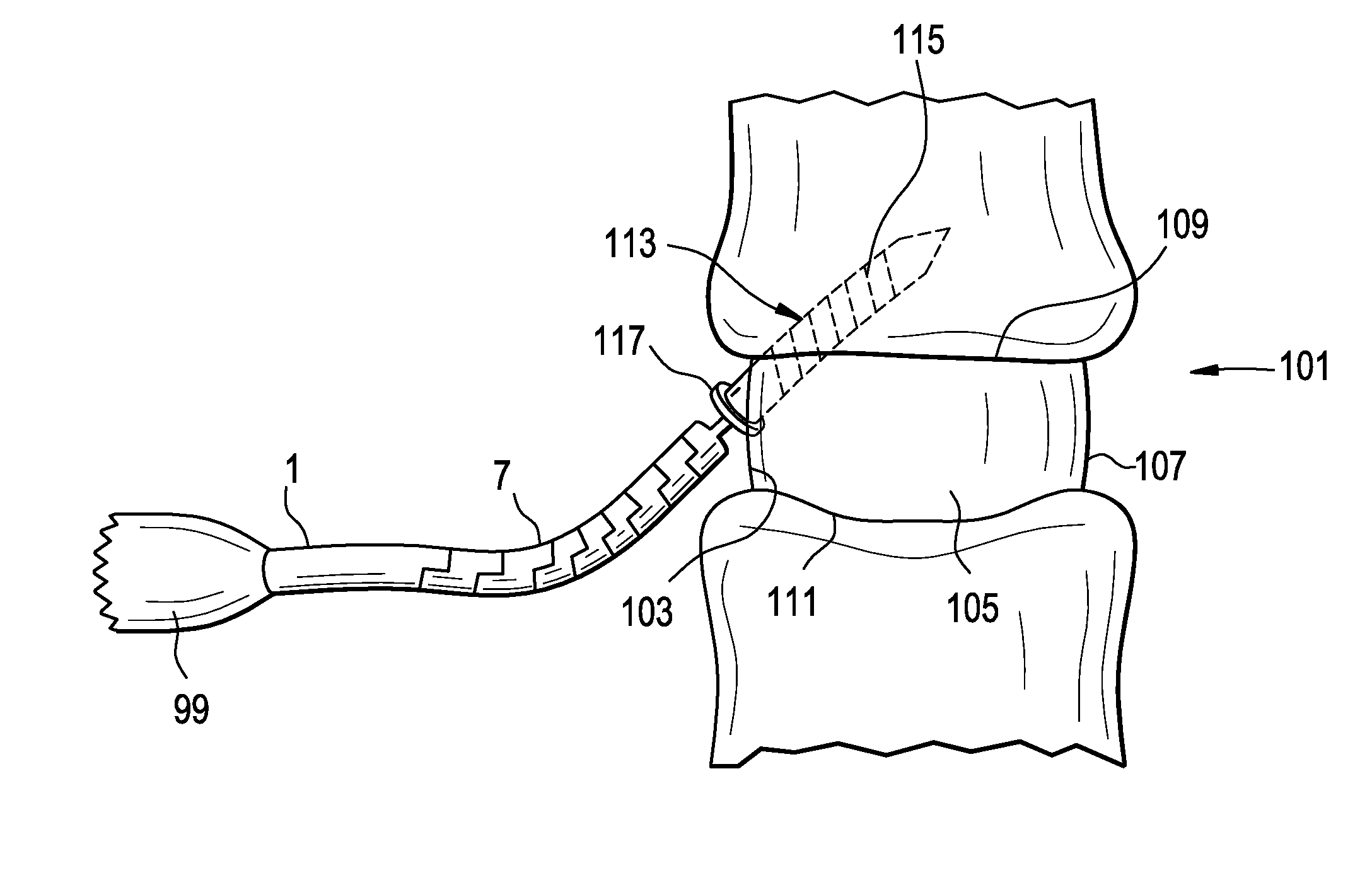
However, screw insertion with a straight-shaft instrument at locations up near a patient's chin or sternum produces some challenging approach angles.
However, one of the challenges associated with this flexible technology is that the flexible shaft is typically straight in its resting configuration.

Method used


Image

  • Flexible Spinal Driver or Drill With A Malleable Core, and/or Fixed Core Radius
  • Flexible Spinal Driver or Drill With A Malleable Core, and/or Fixed Core Radius
  • Flexible Spinal Driver or Drill With A Malleable Core, and/or Fixed Core Radius

Examples


Embodiment Construction

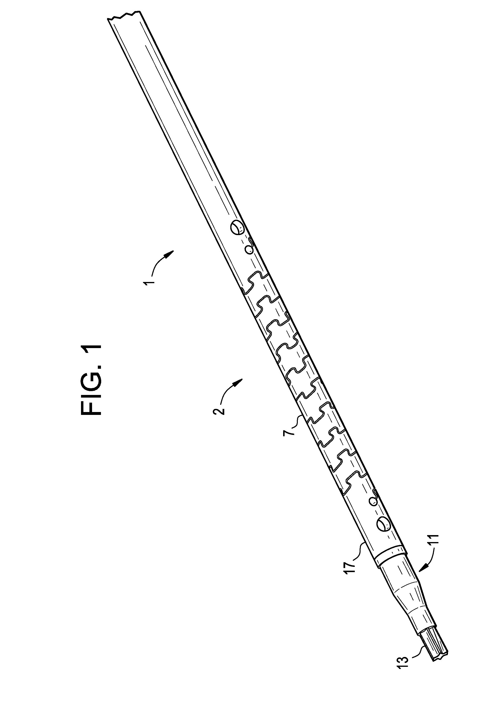
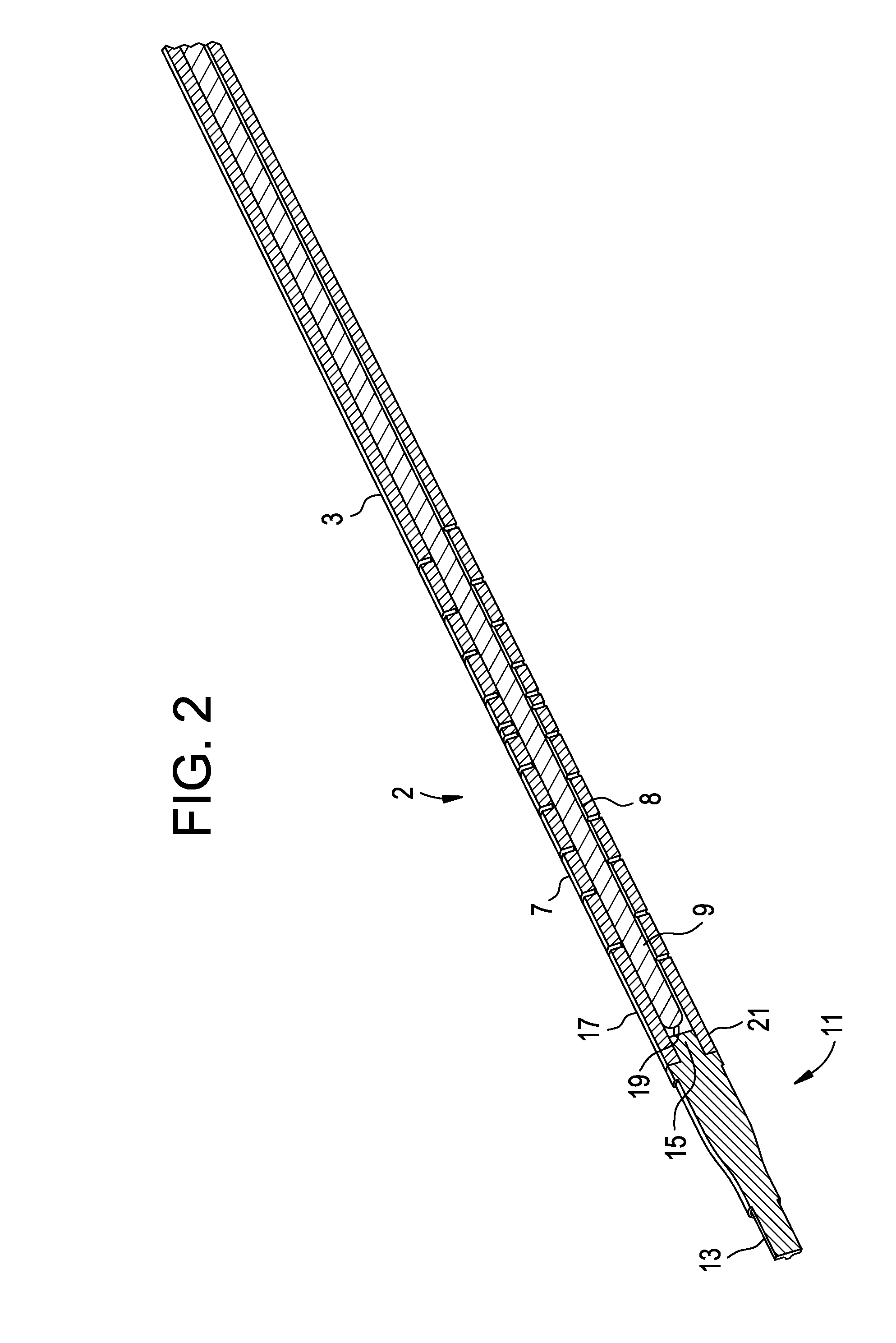
[0024]Now referring to FIGS. 1-3, there is provided a flexible bone screw driver comprising:[0025]a) a rigid proximal portion 1 adapted for connection to a handle 99 or a drill,[0026]b) an intermediate shaft 2 comprising:[0027]i) a plurality of interlocking segments 7, each segment having a throughhole 8, and[0028]ii) a malleable rod 9 extending through the throughhole of each segment, and[0029]c) a distal portion 11 having a working tip 13,

wherein the proximal portion is connected to the intermediate shaft, and

wherein the distal portion of the driver is connected to the intermediate shaft.

[0030]The distal portion of the driver has a distal working tip and a proximal connection portion 15. In general, the working tip is adapted to perform a function on a workpiece via rotation. In some embodiments, the working tip of the driver is adapted to insert bone screws. In others, the working tip of the driver is adapted to drill pilot holes. Preferably, the proximal connection portion is ad...


PUM


Abstract

The improvement is a spinal instrument (preferably, a bone screw driver) having a flexible shaft comprising a plurality of interlocking segments carried on a malleable core rod. The flexible shaft allows a screwdriver handle to be perfectly in-line with the cage inserter if desired, while still taking advantage of the tactile feel and torque transmission of the flex segment in its bent position. Accordingly, a surgeon can limit the amount of retraction and keep the driver handle close to the inserter without having to overcome the forces of the flexible segments' natural straight configuration.

Description

CONTINUING DATA[0001]This application claims priority from co-pending application U.S. Ser. No. 62 / 017,596, filed Jun. 26, 2014, entitled “Flexible Spinal Driver or Drill with a Malleable Core, and or Fix Core Radius”, Martin, Docket No. DSP5074USPSP, the specification of which is incorporated by reference in its entirety.BACKGROUND OF THE INVENTION[0002]When performing a spinal procedure such as an anterior cervical discectomy and fusion (ACDF), the surgeon often has a number of implant options that may achieve the desired clinical outcomes of disc height maintenance and pain relief. Because of their clinical benefits, zero-profile fusion cages that accept bone anchors and are secured to the adjacent anatomy have experienced an increased usage and adoption in the ACDF procedure. These cages typically have angled bone anchors (such as screws) that pass through a portion of the cage's anterior wall and into the adjacent vertebral endplates.[0003]However, if a surgeon were to choose a...

Claims


Application Information

Patent Timeline
IPC IPC(8): A61B17/80A61B17/16A61B17/70
CPCA61B17/1671A61B17/8057A61B17/1631A61B17/8875A61B17/1615A61B2017/00871A61B2017/00867A61B2017/00464A61B17/808A61B2017/00946A61B17/7082A61B17/7074A61B17/7059
Inventor MARTIN, THOMAS
Owner DEPUY SYNTHES PROD INC
Learn More