Hydrostatic Oil Treatment System

a technology of hydrostatic oil treatment and oil treatment tank, which is applied in the direction of gravity filter, feed/displacement of settling tank, water treatment parameter control, etc., to achieve the effects of low engineering cost, convenient transportation and high volume capacity

Active Publication Date: 2015-12-31
BLACK SUEDE HYDRO CARBON PROCESSING
View PDF1 Cites 5 Cited by
  • Summary
  • Abstract
  • Description
  • Claims
  • Application Information

AI Technical Summary

Benefits of technology

[0021]The tanks are preferably arranged as modular units which can be readily transported to and setup at a production site. The operation of the treatment tank substantially at atmospheric pressure has been found to be particularly effective for light oil treatment.
[0022]More particularly, the treatment system and method according to the present invention has found to be advantageous over prior art arrangements in the following manners: no pressure vessels needed, eliminating boiler certification, PSV's, pop tanks, costly turnarounds, and inspections; less on site equipment with high volume capacity; low engineering costs using a modular design; lower on site labour costs; faster on production times; easily set up for water flooding; much lower capital costs; operator friendly and simpler alarms and ESD's, low pressure system with low flowline pressures, reducing or eliminating need for casing gas pumps; no ground disturbance other than compacted gravel pad; smaller site requirements; capable of processing dead emulsion pumped from trucks or flowline; no long centre lines required; all equipment contained with secondary containment; easy clean out hopper bottom design; and remote site installation ability.

Problems solved by technology

Although effective, such pressure vessels require boiler certification, PSV's, pop tanks, costly turnarounds for setup and maintenance, and inspections to be performed.

Method used


Image

  • Hydrostatic Oil Treatment System
  • Hydrostatic Oil Treatment System
  • Hydrostatic Oil Treatment System

Examples


first embodiment

[0076]Although various embodiments are shown in the accompany figures, the features of FIGS. 1 through 3 will first be described.

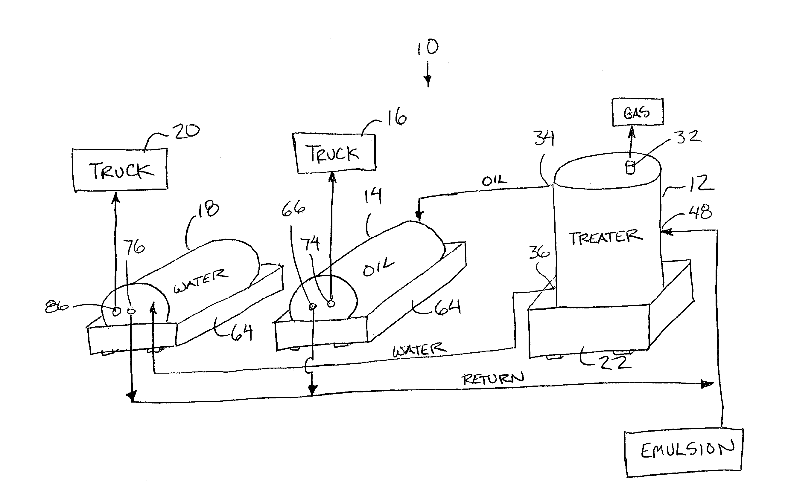
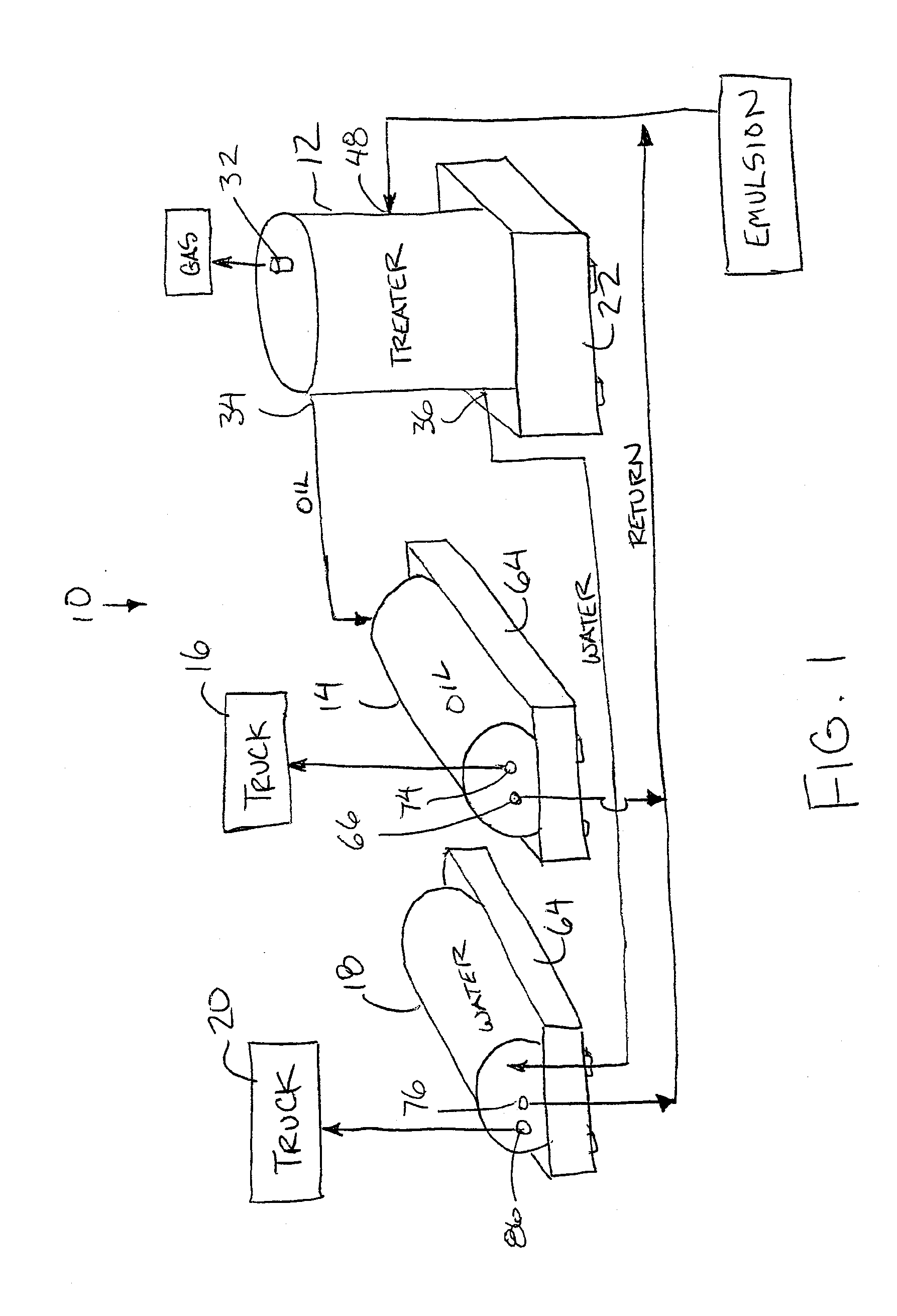
[0077]As generally represented in FIG. 1, the system includes a treatment tank 12 which receives the produced emulsion therein. Oil is transferred from the treatment tank 12 to a separate oil tank 14 for subsequent discharge to a transport truck 16 as required. Oil is also separated from the emulsion in the treatment tank for being transferred to a separate water tank 18. Collected water in the water tank can similarly be discharged to a transport tanker truck 20.

[0078]The treatment tank 12 is a vertically oriented tank so as to be vertically elongated. The tank includes a secondary containment 22 having a platform skid base with integral containment walls about a perimeter thereof such that the skid base and integral containment walls are suitably sized to form a secondary containment to the vertical tank. The secondary containment is also readily transpo...

second embodiment

[0101]Turning now to FIGS. 4 through 8, the treatment system 10 in this instance again comprises a treatment tank 12, an oil tank 14 and a water tank 18; however, the oil tank 14 in this instance comprises a first oil tank 14A and a second oil tank assembly 14B in series with one another. Furthermore, all of the tanks in his instance comprise horizontally elongated tanks having a cylindrical wall extending horizontally between two opposed vertical end walls.

[0102]The system 10 in this instance further includes a gas separator 90 connected in series with the production inlet 48 of the treatment tank so as to remove some gas from the emulsion prior to the emulsion. The gas separator comprises a tank having an inlet for receiving the emulsion, a gas outlet through which gas is removed from the tank, and an oil outlet through which the degassed oil emulsion is removed from the tank for subsequent communication with the production inlet of the treatment tank. The tank further includes a ...


PUM

PropertyMeasurementUnit
atmospheric pressureaaaaaaaaaa
elevationaaaaaaaaaa
gravity dischargeaaaaaaaaaa

Abstract

A hydrocarbon emulsion treatment system includes a treatment tank having a gas vent for operating the treatment tank near atmospheric pressure. The treatment tank separates water and oil in the emulsion for discharge to separate water and oil tanks respectively. According to a preferred embodiment, the treatment tank and the oil tank are supported on a common frame including an integral secondary containment structure providing secondary containment to both the treatment tank and the oil tank. The treatment tank is supported at greater elevation than the oil tank to allow the flow of oil from the treatment tank to the oil tank primarily under force of gravity.

Description

[0001]This application claims the benefit under 35 U.S.C. 119(e) of U.S. provisional application Ser. No. 62 / 018,082, filed Jun. 27, 2014.FIELD OF THE INVENTION[0002]The present invention relates to a system and a method of use of the system for treating a produced hydrocarbon emulsion, for example produced light oil, to separate oil, water, and gas components in a treatment chamber which is maintained substantially at or near atmospheric pressure.BACKGROUND[0003]Hydrocarbons are typically produced from the ground in the form of an emulsion of various fractions of oil, water and gases. Typically it is desirable to perform some initial treatment of the produced fluids to remove the bulk of the water and gas content prior to delivery to a treatment plant. The produced fluids can be initially treated at the production site, or alternatively transferred to an intermediate site for initial treatment to remove the bulk of the water and gas content.[0004]Initial treatment of light and heav...

Claims


Application Information

Patent Timeline
Patent Type & Authority Applications(United States)
IPC IPC(8): B01D17/02C10G33/06C02F1/40
CPCB01D17/0214B01D19/0063C10G33/06C02F2101/32B01D17/12C02F2101/325C02F1/02C02F1/20C02F1/24C02F2103/10C02F2103/365C02F2209/03C02F2209/42C02F1/006C02F1/40
Inventor WARNER, MICHAELANDRES, DEAN
Owner BLACK SUEDE HYDRO CARBON PROCESSING
Why Eureka
Try Eureka