Eureka AIR delivers breakthrough ideas for toughest innovation challenges, trusted by R&D personnel around the world.

System, apparatus and method for hybrid function micro welding

a technology of hybrid function and micro welding, applied in the field of micro welding, can solve the problems of affecting the effect of welding, scratching or nicking the wire, and making the stripping wire more vulnerable to breakag

Active Publication Date: 2015-12-31
JABIL INC
View PDF8 Cites 60 Cited by
  • Summary
  • Abstract
  • Description
  • Claims
  • Application Information

AI Technical Summary

Benefits of technology

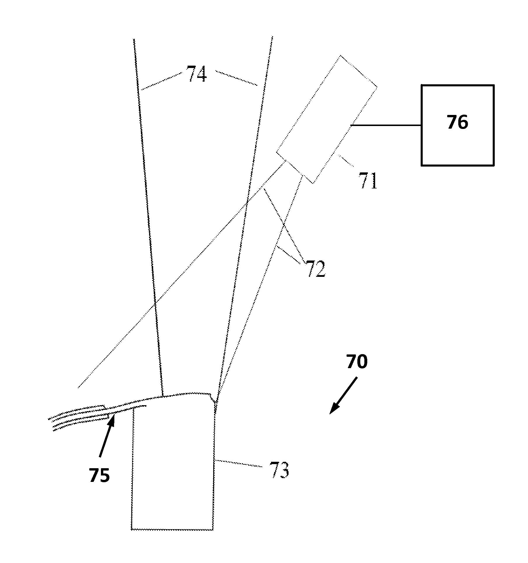
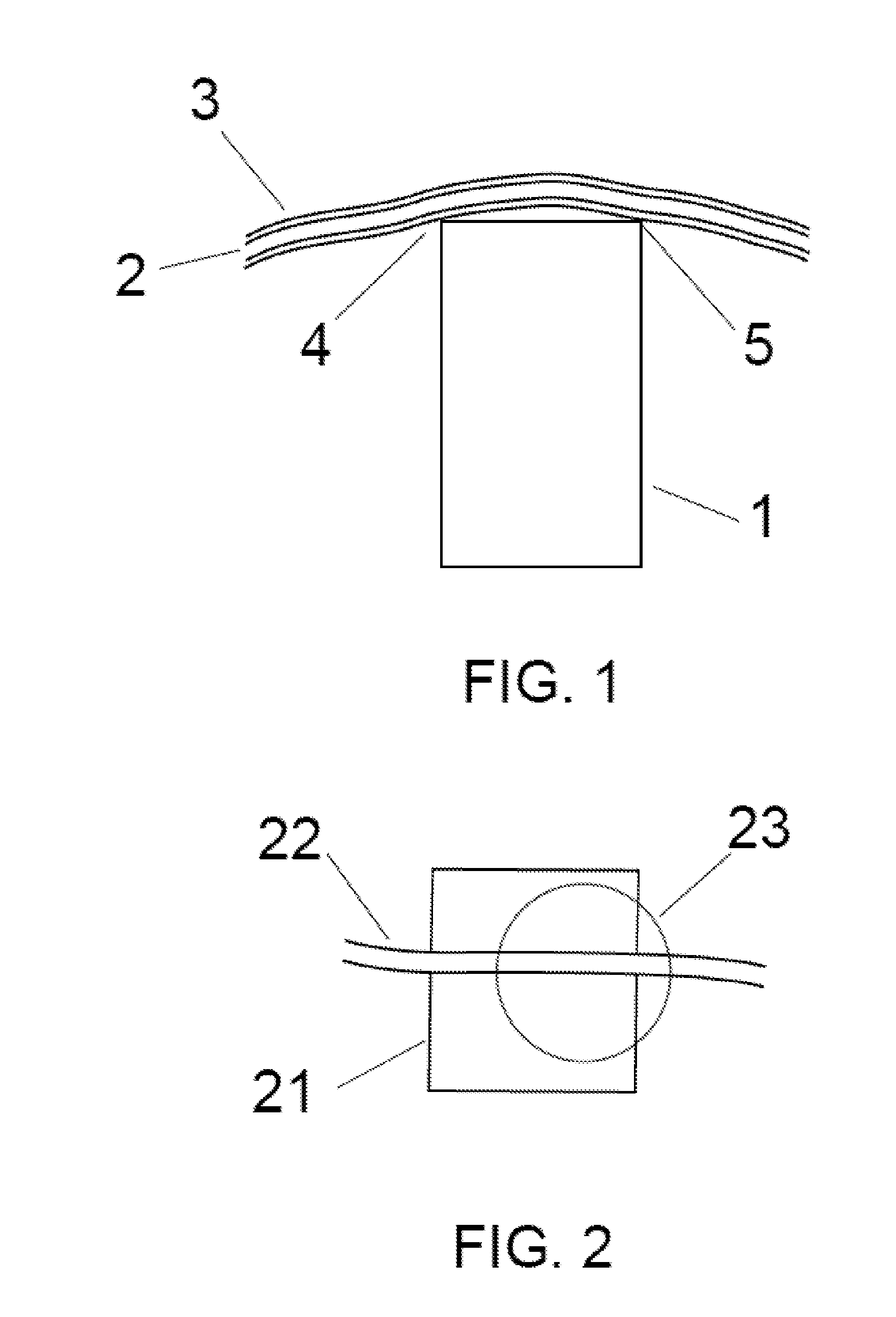
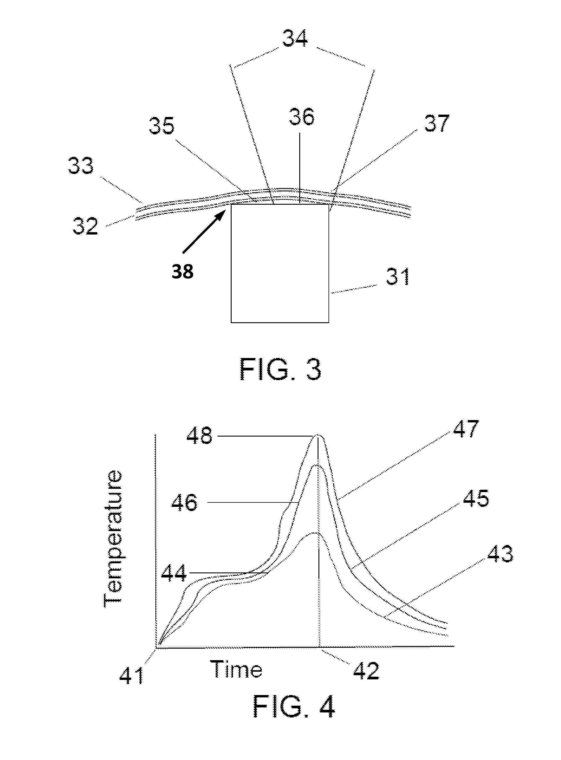
This patent describes an apparatus, system, and method for micro welding, which involves heating an area of an insulated wire or object using a laser to simultaneously generate multiple heating regions. The first region is used to remove the insulation covering the wire, the second region is used to weld the wire to a termination point, and the third region is used to detach the wire from the termination point. The technical effects of this method include improved precision and control during micro welding, reduced damage to the insulation layers, and improved durability of the welded area.

Problems solved by technology

While the wire coatings are designed to insulate and protect the wires, the coatings may be difficult to strip and prepare for effective attachment to other components, and / or require multi-step processes to both strip and prepare the wires, as referenced above.
Each of these methods possesses certain disadvantages, such as scratching or nicking the wire.
Thermal annealing of the wire may render the stripped wire more vulnerable to breakage as it is subsequently formed in preparation for soldering or welding.
After attachment, the resulting connection may continue to be weak and less reliable.
However, the wires in such instances remain at risk of damage from the solder itself, at least because the increased exposure time of the wire exposed during the solder stripping process.
Further, as the insulation is removed by exposure to molten solder, a chemical reaction between the tin in the solder and the copper in the wire may degrade the mechanical strength and electrical conductivity of the joint.
The drawbacks of the aforementioned insulation removal techniques are particularly present for very small gage wires, such as AWG 30 and smaller.
The above drawbacks are greatly increased for small gage wires because the volume of insulation coating material is large as compared to the underlying wire.
Furthermore, the surface area of the wire is large compared to the volume of the wire, which increases the rate of chemical reaction with the solder and thereby risks loss of strength and conductivity during the attachment process.
The process of mechanically securing the wires requires additional process steps which add to the complexity, time and expense of the assembly process.

Method used


Image

  • System, apparatus and method for hybrid function micro welding
  • System, apparatus and method for hybrid function micro welding
  • System, apparatus and method for hybrid function micro welding

Examples


Embodiment Construction

[0023]The figures and descriptions provided herein may have been simplified to illustrate aspects that are relevant for a clear understanding of the herein described devices, systems, and methods, while eliminating, for the purpose of clarity and brevity, other aspects that may be found in typical similar devices, systems, and methods. Those of ordinary skill may thus recognize that other elements and / or operations may be desirable and / or necessary to implement the devices, systems, and methods described herein. But because such elements and operations are known in the art, and / or because they do not facilitate a better understanding of the present disclosure, a discussion of such elements and operations may not be provided herein. However, the present disclosure is deemed to include all such elements, variations, and modifications to the described aspects that would be known to those of ordinary skill in the art.

[0024]Exemplary embodiments are provided throughout so that this discl...


PUM

PropertyMeasurementUnit
Wavelengthaaaaaaaaaa
Electrical conductoraaaaaaaaaa

Abstract

An apparatus, system and method for micro welding, wherein insulated object, such as a wire, that includes a metallic conductor that is at least partially covered by one or more layers of insulation, is positioned across a termination point. A laser beam may be applied to an area of the insulated object overlapping the termination point, wherein the applied laser beam is configured to substantially simultaneously (i) ablate the one or more layers of insulation in a first region of the area, (ii) weld the metallic conductor to the termination point in a second region of the area, and (iii) detach a portion of the object from the termination point in a third region of the area.

Description

CROSS-REFERENCE TO RELATED APPLICATIONS[0001]This application claims priority to U.S. Provisional Application Ser. No. 62 / 018,516, filed Jun. 27, 2014, entitled “Hybrid Micro-Welding Process.”BACKGROUND[0002]1. Field of the Disclosure[0003]The present disclosure is generally directed to micro welding, and more specifically to technologies and techniques for attaching components, such as wire, using controlled removal and fusion of material using energy such as laser applied in the disclosed exemplary manners to strip, weld and cut fine gage wires to connection points in a single operational step.[0004]2. Description of the Background[0005]The term “micro welding” typically refers to the precise placement of connective metals and the application of energy to form welds that may be less than 100 μm wide. Usually performed under a microscope for accuracy, the actual welding process in some cases may be similar to normal welding, but on a much smaller scale. In most high-volume industri...

Claims


Application Information

Patent Timeline
IPC IPC(8): B23K26/21B23K26/03B23K35/02B23K26/38B23K26/362
CPCB23K26/36B23K2101/38B23K35/0272B23K26/21
Inventor STERLING, WILLIAM DOUGLASSU, CHAOGU, GONGEN
Owner JABIL INC
Why Eureka
Eureka Blog
Learn More