Engine stop control apparatus and engine stop control method

a technology of control apparatus and control method, which is applied in the direction of electrical control, engine starters, instruments, etc., can solve the problems of excessive power consumption, torque generated by short-circuit braking, and the inability to accurately control the stop position to the appropriate position, etc., and achieves high energy efficiency and small power consumption

Active Publication Date: 2015-12-31
MITSUBISHI ELECTRIC CORP
View PDF0 Cites 13 Cited by
  • Summary
  • Abstract
  • Description
  • Claims
  • Application Information

AI Technical Summary

Benefits of technology

[0024]According to the engine stop control apparatus of the one embodiment of the present invention, the engine stopping section first selects, when the engine stop condition is satisfied, the power-generation braking mode in which the power-generation braking torque is applied to the engine by the power generation operation of the generator, to thereby apply the power-generation braking torque to the engine, and then selects the short-circuit braking mode in which the short-circuit braking torque is applied to the engine by short-circuiting each energization phase of the armature coil with the semiconductor switch and by causing the field current to flow through the field coil, to thereby apply the short-circuit braking torque to the engine.
[0025]Further, the engine stop control method according to the one embodiment of the present invention includes: selecting, when the engine stop condition is satisfied, the power-generation braking mode in which the power-generation braking torque is applied to the engine by the power generation operation of the generator; and selecting, subsequently to the selecting of the power-generation braking mode, the short-circuit braking mode in which the short-circuit braking torque is applied to the engine by short-circuiting each energization phase of the armature coil with the semiconductor switch, and by causing the field current to flow through the field coil.
[0026]Accordingly, it is possible to obtain the engine stop control apparatus and the engine stop control method, which are capable of stopping the engine accurately at the target stop position without causing the swing-back, are small in power consumption, and have the high energy efficiency.

Problems solved by technology

Therefore, there has been a problem in that the engine stop position cannot be accurately controlled to the appropriate position.
On the other hand, the torque due to the short-circuit braking is generated by consuming the electromotive force of the armature coil therein.
Therefore, excess power is consumed.
Further, because the power-generation braking torque is dependent on the battery voltage and the short-circuit braking torque is independent of the battery voltage, it is understood that braking torque characteristics during a power-generation braking mode and braking torque characteristics during a short-circuit braking mode do not generally match with each other.
In this method, as described above, a sufficient power-generation braking torque cannot be generated in a low rotation range.

Method used


Image

  • Engine stop control apparatus and engine stop control method
  • Engine stop control apparatus and engine stop control method
  • Engine stop control apparatus and engine stop control method

Examples


first embodiment

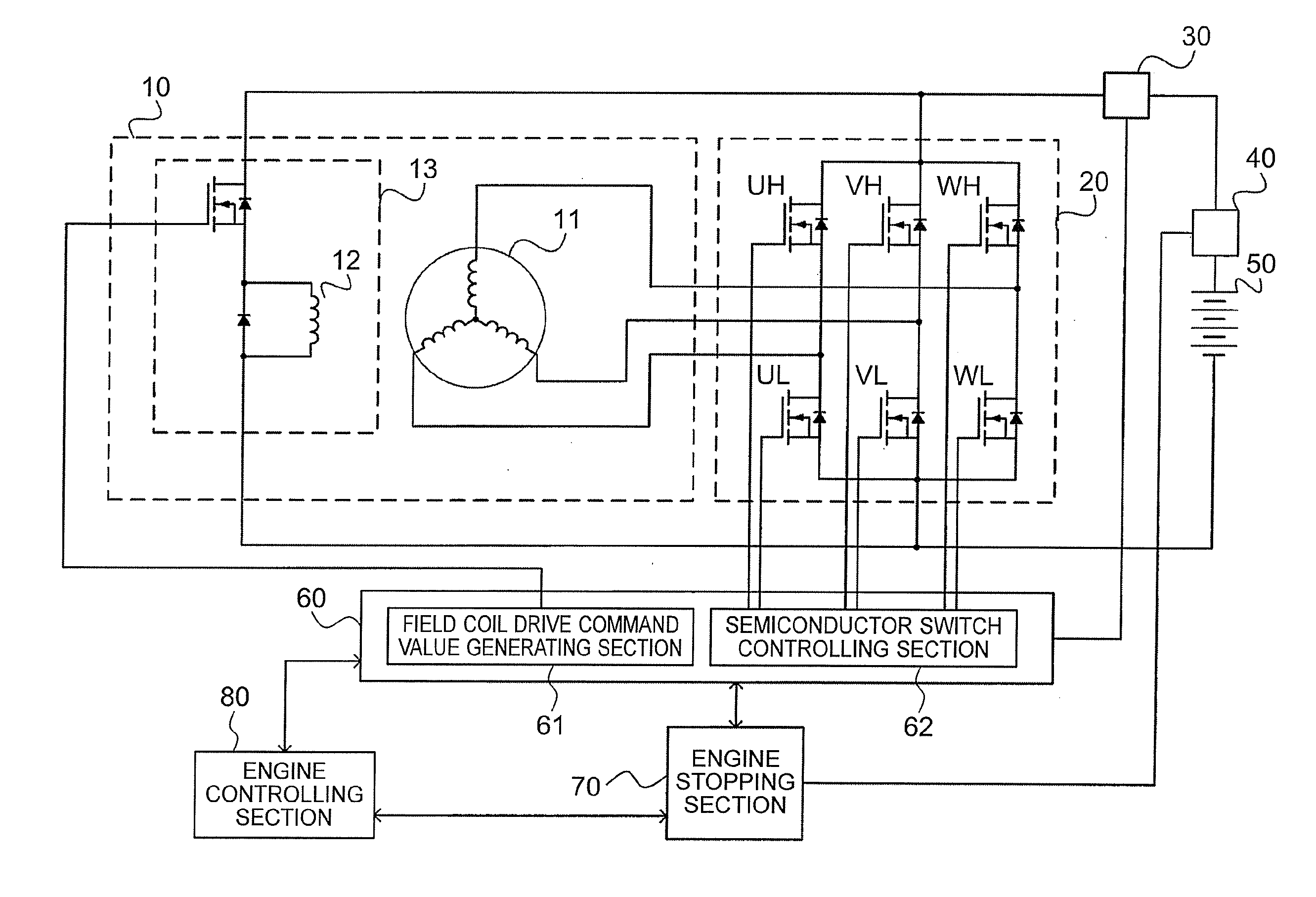
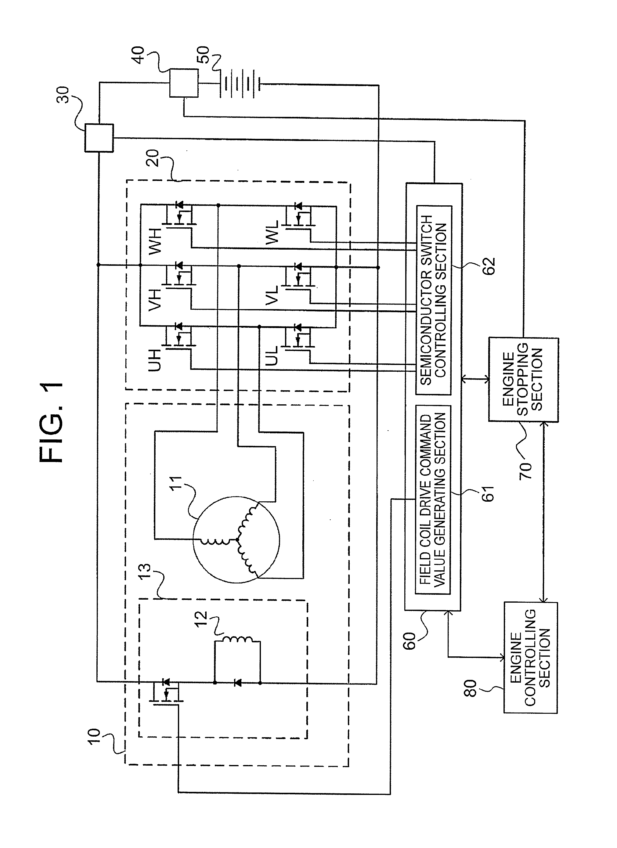
[0037]FIG. 1 is a configuration diagram of an engine stop control apparatus according to a first embodiment of the present invention. In FIG. 1, the engine stop control apparatus includes a field coil-type generator 10 (hereinafter simply referred to as “generator 10”), an armature coil driving circuit 20, a generator power sensor 30, a battery voltage sensor 40, a battery 50, a generator driving section 60, an engine stopping section 70, and an engine controlling section 80.

[0038]The generator 10 includes an armature coil 11, a field coil 12, and a field coil driving circuit 13. The armature coil driving circuit 20 includes six semiconductor switches (UH, VH, WH, UL, VL, and WL). Further, the generator driving section 60 includes a field coil drive command value generating section 61 and a semiconductor switch controlling section 62.

[0039]In the generator 10, the armature coil 11 is a stator, and the field coil 12 is a rotator. Further, the energization phase to be energized by the...


PUM


Abstract

An engine stopping section first selects, when an engine stop condition is satisfied, a power-generation braking mode in which a power-generation braking torque is applied to the engine by a power generation operation of the generator, to thereby apply the power-generation braking torque to the engine, and then selects a short-circuit braking mode in which a short-circuit braking torque is applied to the engine by short-circuiting each energization phase of an armature coil with a semiconductor switch and by causing a field current to flow through a field coil, to thereby apply the short-circuit braking torque to the engine.

Description

TECHNICAL FIELD[0001]The present invention relates to an engine stop control apparatus and an engine stop control method, which are to be applied to a vehicle having an idle reduction function in which, when a predetermined engine stop condition is satisfied while the vehicle is traveling, fuel supply to an engine is stopped, and, when a predetermined engine restart condition is satisfied thereafter, the number of revolutions of the engine is increased with use of a starting device to restart the fuel supply to the engine.BACKGROUND ART[0002]In a vehicle having an idle reduction function, when engine restart is requested through a driver's driving operation, quick performance of restarting the engine instantly is required. At this time, fuel is injected into a cylinder in a stopped state in an expansion stroke to enable quick restart. It is known that stopping the engine in a specific crank angle range among crank angle ranges in the expansion stroke improves the restarting performa...

Claims


Application Information

Patent Timeline
Patent Type & Authority Applications(United States)
IPC IPC(8): F02D41/04F02D29/06F02N11/04F02D29/02
CPCF02D29/02F02D29/06F02D41/042F02N11/04F02N19/005F02D2250/06F02N2011/0896F02N2019/008F02N2200/021
Inventor KAMIOKA, NOZOMUWACHI, SATOSHIDATE, TOSHIAKISAGAYAMA, NORIYA
Owner MITSUBISHI ELECTRIC CORP
Why Eureka
Try Eureka