
Phased array system capable of computing gains for non-measured calibration points

Inactive Publication Date: 2015-12-31
OLYMPUS SCI SOLUTIONS INC
View PDF2 Cites 14 Cited by
  • Summary
  • Abstract
  • Description
  • Claims
  • Application Information

AI Technical Summary

Benefits of technology

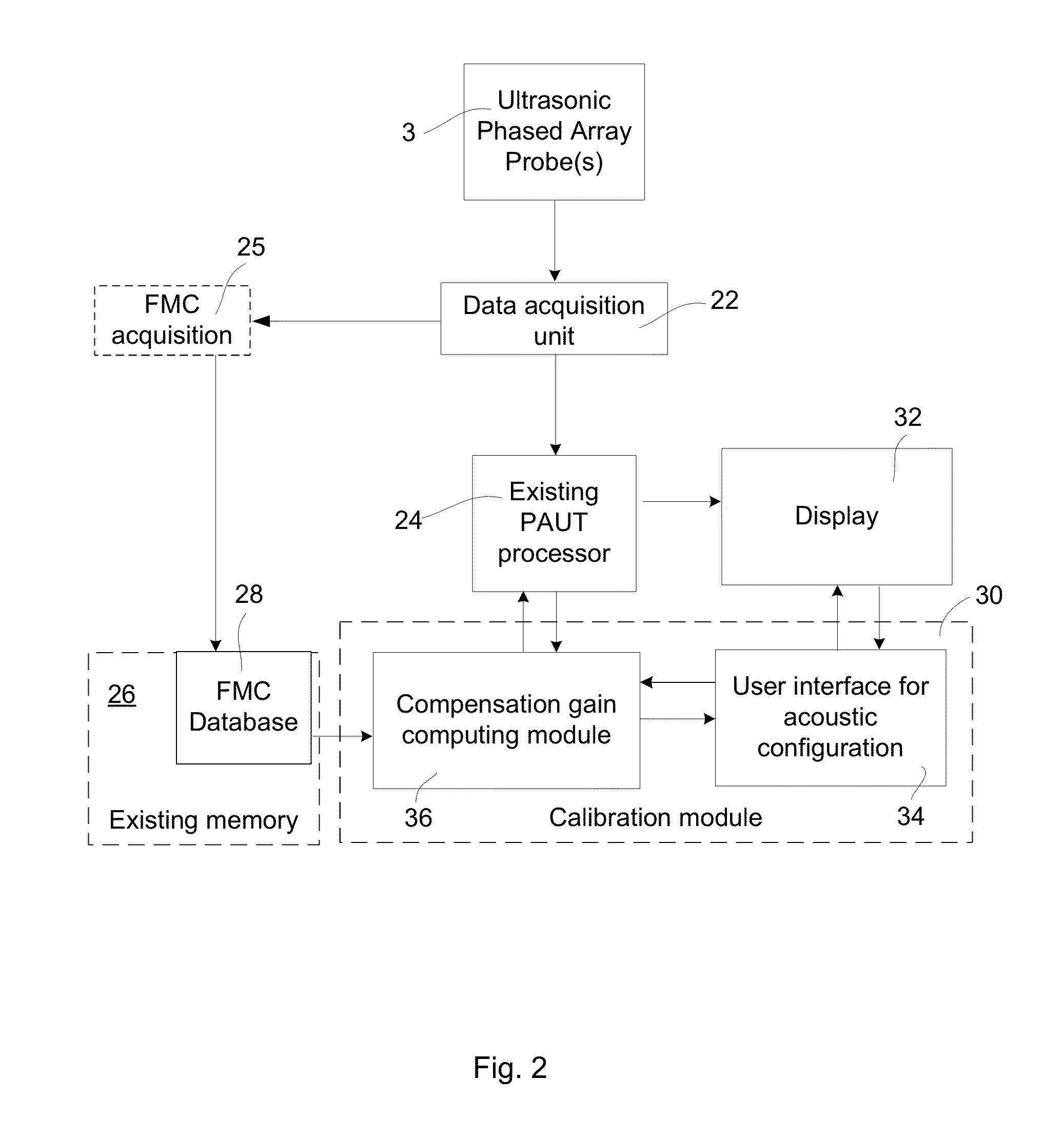
The invention simplifies the calibration process of a probe by predicting and adapting the gain compensation to be applied in the display view of the probe. It uses a reference calibration database acquired using a specific method to reconstruct any beam configuration and generate gain compensation maps for a set of probe and wedge configurations. By taking into account different material sound velocity, attenuation, and instrumentation sensitivity, the predicted gain compensation is adapted to the specifics of the user's configuration. This results in a calibration process that requires less user manipulation and is tolerant to user imprecisions.

Problems solved by technology

This is detrimental to quality of the UT inspection and is typically corrected either by a distance amplitude curve (DAC) or a time corrected gain (TCG).
The requirement to compensate the gain for both the angle and the sound path length increases the complexity of the PAUT system calibration, which then becomes a time consuming task in the inspection process, requiring skilled and careful technicians.
Another aspect to consider is the large differences in gain level required over the angular range, which typically makes it impossible to conduct the calibration scan for one depth with a single gain configuration.

Method used


Image

  • Phased array system capable of computing gains for non-measured calibration points
  • Phased array system capable of computing gains for non-measured calibration points
  • Phased array system capable of computing gains for non-measured calibration points

Examples


Embodiment Construction

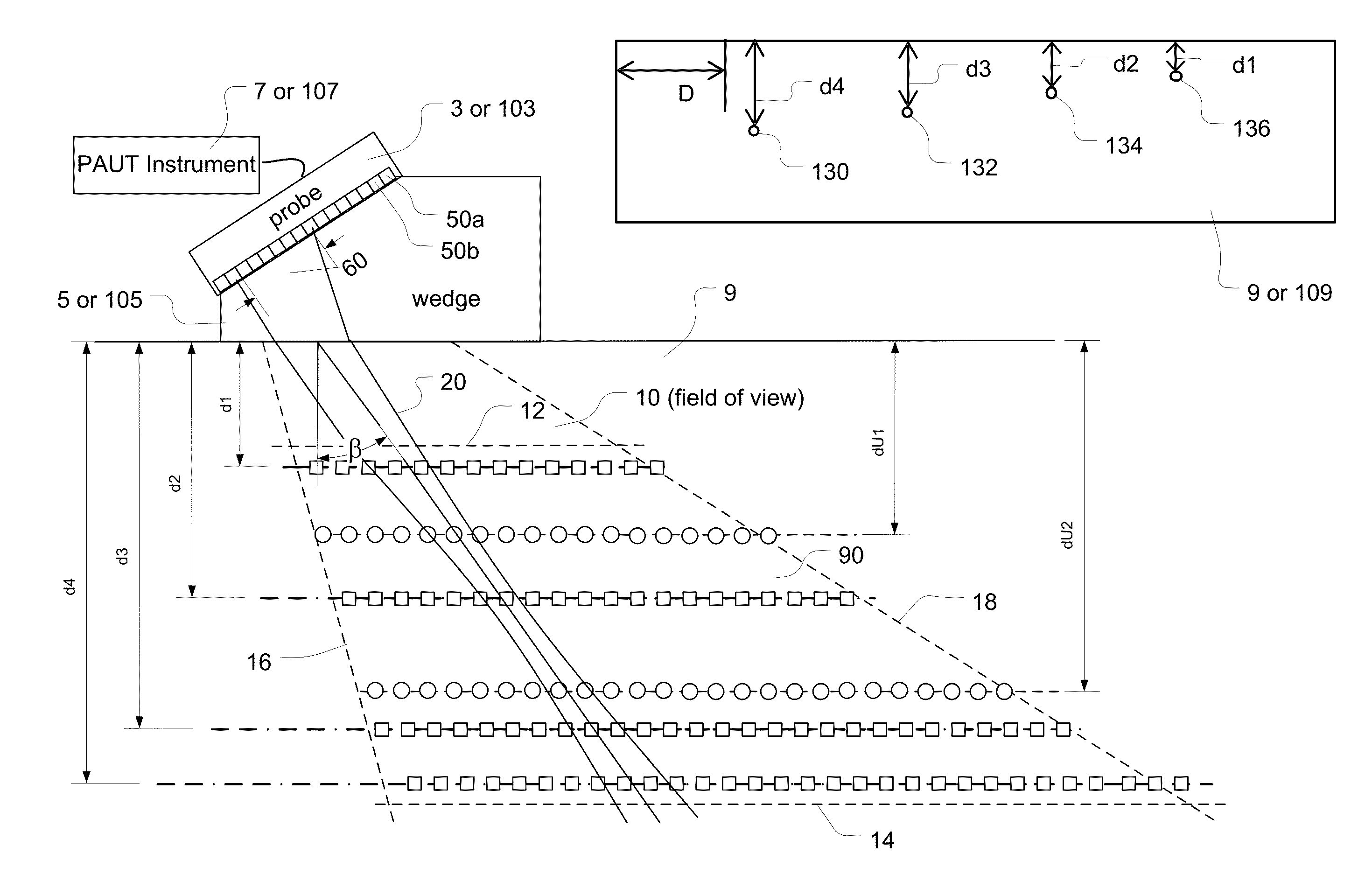
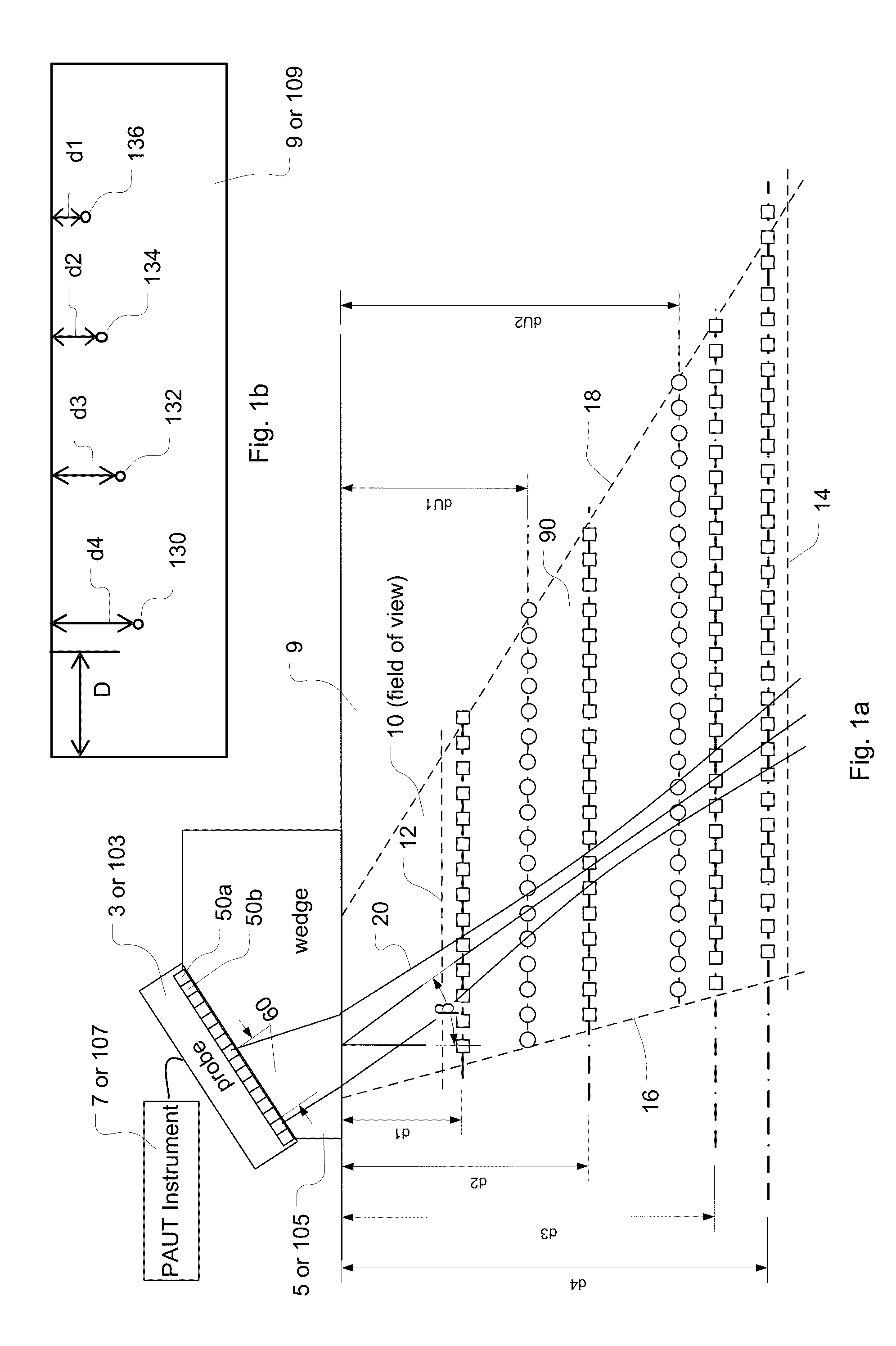
[0023]FIGS. 1a and 1b depict a conceptual representation of the present disclosure showing a PAUT configuration, and including building an off-line database, such as an FMC database. The process of populating the FMC database by obtaining ultrasonic phased array data from a standard calibration block is widely known. It usually involves use of a single axis scanner scanning a series of predetermined known indications at known depths (shown as the square legends in FIG. 1a), and obtains a series of calibration data points acquired under laboratory conditions. Also shown in FIGS. 1a and 1b is the novel aspect of the present disclosure, which is to produce computed calibration points (shown as the circle legends) covering the full field of view 10 of the inspection with those standard calibration points as well as with a limited amount of user data.

[0024]As seen in FIGS. 1a and 1b, calibration points in field of view 10 denoted by square legends are automatically generated from a previ...


PUM


Abstract

Disclosed is a calibration method and system for non-destructive testing and inspection (NDT / NDI). The method and system involve establishment of a reference database by conducting FMC acquisition on a first calibration block having standardly known indications with a first series of depths and under a laboratory standard calibration condition. Then phased-array operation is conducted on a second calibration block, which is substantially the same as the first block, having indications with a series of corresponding user measured depths and under a second calibration condition as close to the laboratory condition as possible. The calibration is then made with the gain compensation calculated based on the response signals from the indications of the second block, the first series of gain data from the reference database, and the user measured depths for the corresponding indications under the second calibration condition.

Description

CROSS-REFERENCE TO RELATED APPLICATIONS[0001]This application claims the benefit and priority of U.S. Provisional patent application Ser. No. 62 / 018,271 filed Jun, 27, 2014 entitled A PHASED ARRAY SYSTEM CAPABLE OF COMPUTING GAINS FOR NON-MEASURED CALIBRATION POINTS, the entire disclosure of which is incorporated herein by reference.FIELD OF THE INVENTION[0002]The invention relates to an instrument for non-destructive testing and or inspection (NDT / NDI), more particularly to an improvement in the calibration of the gain compensation of a phased array (PA) ultrasound instrument utilizing full-matrix-capture of the PA data.BACKGROUND OF THE INVENTION[0003]During NDT / NDI testing, sound traveling through metal from an ultrasound (UT) probe goes through the process of attenuation, absorption and scattering. Flaws of identical size at different depths result in different amplitudes of sound returning to the probe. This is detrimental to quality of the UT inspection and is typically correc...

Claims


Application Information

Patent Timeline
IPC IPC(8): G01N29/44G01N29/26
CPCG01N29/069G01N29/30G01N2291/044G01N29/4463G01N29/262G01N29/4427
Inventor ZHANG, JINCHILEPAGE, BENOIT
Owner OLYMPUS SCI SOLUTIONS INC
Learn More