
Non-mechanical beam steering tracking system

a technology of beam steering and tracking system, applied in the field of non-mechanical beam steering tracking system, can solve the problems of large size, weight, power consumption, and scanning time of mechanical gimbals as alternatives, and achieve the effects of less hardware, less complexity, and less complexity, size, weight, cost, scanning-time and mechanical breakdown

Active Publication Date: 2015-12-31
THE GOVERNMENT OF THE UNITED STATES OF AMERICA AS REPRESENTED BY SEC OF THE NAVY
View PDF2 Cites 20 Cited by
  • Summary
  • Abstract
  • Description
  • Claims
  • Application Information

AI Technical Summary

Benefits of technology

The invention provides a way to achieve both coarse and continuous fine steering of a laser beam with a single device. This approach is simpler, lighter, and cheaper than traditional methods, and can provide the same precision pointing and wide field of regard. It also avoids the need for multiple devices and the associated costs and limitations of traditional gimbals.

Problems solved by technology

Mechanical gimbals as an alternative have the disadvantages of much greater size, weight, power consumption, and scanning time.

Method used


Image

  • Non-mechanical beam steering tracking system
  • Non-mechanical beam steering tracking system
  • Non-mechanical beam steering tracking system

Examples


Embodiment Construction

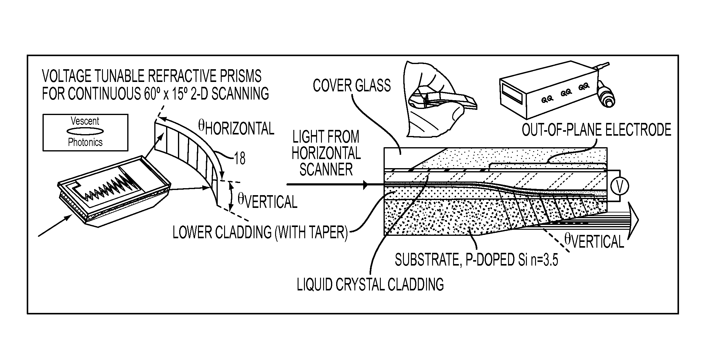
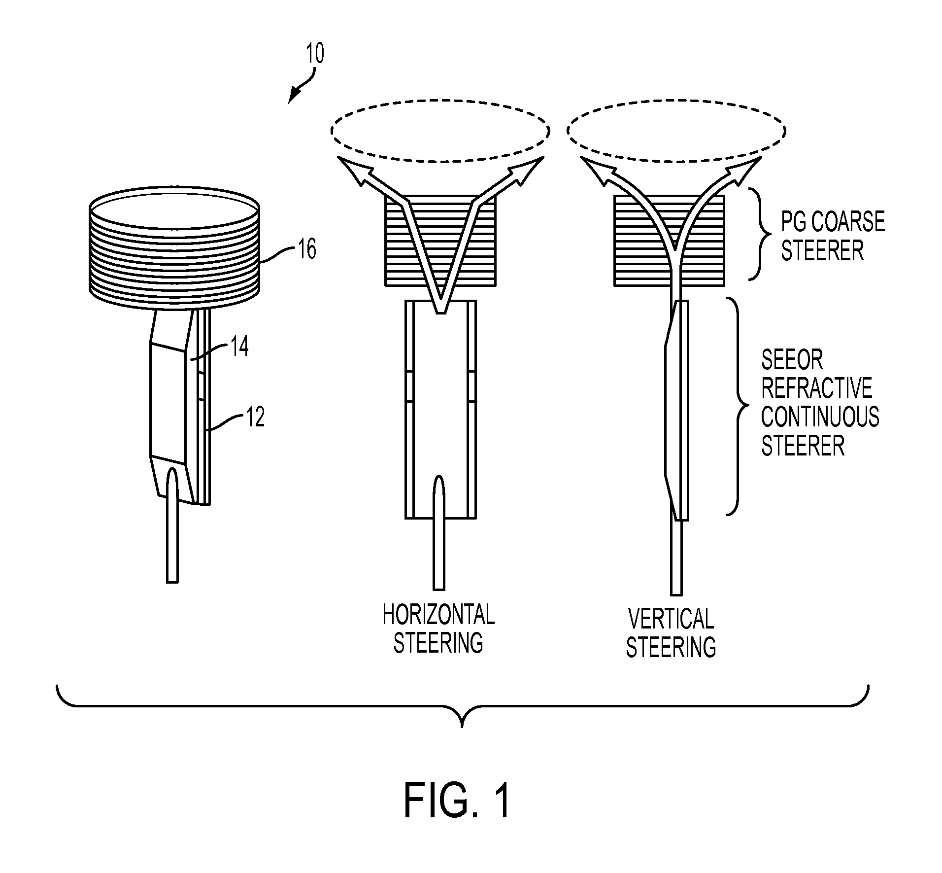
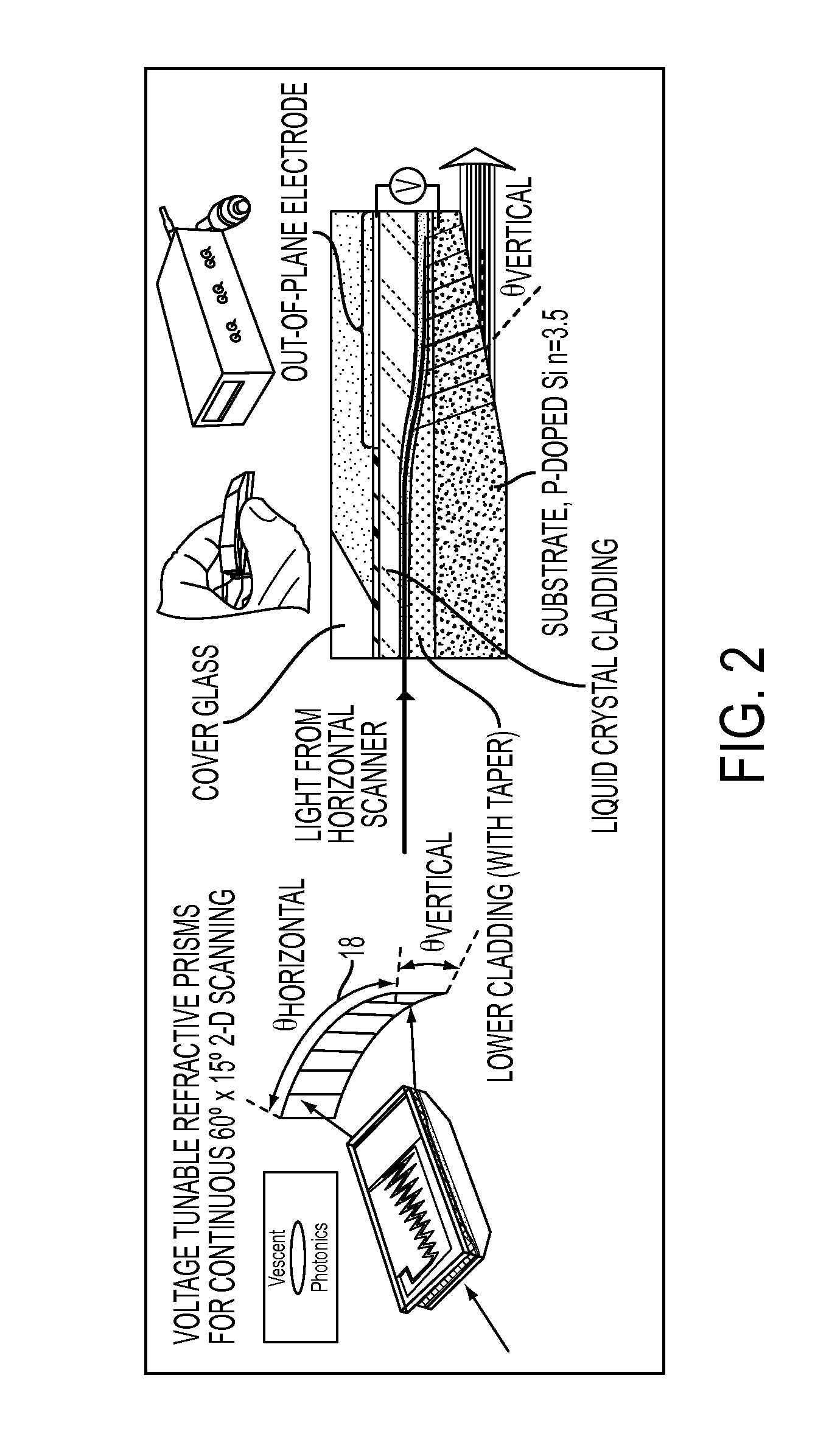
[0011]Referring now to FIG. 1 showing one embodiment of the invention, a non-mechanical beam steering tracking system (“NMBS”) 10 couples a continuous steering component 12, consisting of a compact liquid crystal (LC)-clad optical waveguide 14, to a coarse steering polarization grating (PG) 16 to create a purely electro-optic (EO) steerer exceling in throughput, field-of-regard (FOR), scanning time, and clear aperture. The former technology is ideal for compact, rapid continuous steering while the latter technology is most favorable for discrete steering to access large FORs. The preferred embodiment of the NMBS 10 is to propagate and send a laser beam through the optical waveguide 14 covering 60°×15° and then into a coarse steering PG stack to address the full FOR.

[0012]The continuous steering component 12 can be a Steerable Electro-Evanescent Optical Refractor (SEEOR) as shown in FIG. 2, which provides the giant electro-optic phase control (>2 mm) provided by LC-clad optical waveg...


PUM

PropertyMeasurementUnit
optical widthaaaaaaaaaa
specific-angleaaaaaaaaaa
mechanical gimbalsaaaaaaaaaa

Abstract

A non-mechanical optical beam steering device includes one or more polarization gratings (PG) coupled to one or more Steerable Electro-Evanescent Optical Refractors (SEEOR). It provides the coarse steering advantage of the PG and also the continuous fine steering advantage of the SEEOR. The result is far less complexity, size, weight, and cost over the alternative non-mechanical beam steering approaches as well as considerably less complexity, size, weight, cost, scanning-time, and mechanical breakdown over the more traditional gimbaled mirrors commonly used.

Description

CROSS-REFERENCE TO RELATED APPLICATIONS[0001]This Application claims the benefit of U.S. Provisional Application 61 / 783,008 filed on Mar. 14, 2013 and incorporated herein by reference.FIELD OF THE INVENTION[0002]The invention is directed to a non-mechanical beam steering tracking system (NMBS), and more particularly to an NMBS combining a steerable electro-evanescent optical refractor and polarization gratings.BACKGROUND OF THE INVENTION[0003]Commercial and Military Laser devices generally use mechanically controlled (gimbaled) mirrors to aim, steer, and scan laser beams. Such mechanically controlled systems have several disadvantages: (1) weight, (2) size, (3) power consumption, (4) mechanical breakdown, and (5) time delays in steering. Considerable resources have been spent by commercial and military research to find acceptable alternatives to this gimbaled approach which can also cover wide fields of regard with high accuracy “fine” beam pointing.[0004]Two promising approaches to...

Claims


Application Information

Patent Timeline
Patent Type & Authority Applications(United States)
IPC IPC(8): G02F1/295G02B6/27G02F1/13
CPCG02F1/0118G02F1/29G02F2001/291G02F1/292G02F1/1326G02F1/295G02F1/1347G02B6/2753G02F1/291
Inventor AUXIER, JASONDUNAY, CHRISTOPHERPAULI, MYRON R.
Owner THE GOVERNMENT OF THE UNITED STATES OF AMERICA AS REPRESENTED BY SEC OF THE NAVY
Learn More