Organic light emitting display for compensating for variations in electrical characteristics of driving element

a light-emitting display and driving element technology, applied in the direction of instruments, static indicating devices, etc., can solve the problems of difficult to realize a desired image, complex configuration of the pixel circuit, and variations from pixel to pixel, so as to achieve shorten the sensing time and improve the sensing accuracy

Active Publication Date: 2015-12-31
LG DISPLAY CO LTD
View PDF9 Cites 53 Cited by
  • Summary
  • Abstract
  • Description
  • Claims
  • Application Information

AI Technical Summary

Benefits of technology

[0016]An aspect of the present invention is to provide an organic light emitting display which offers shorter sensing time and higher sensing accuracy when sensing variations in electrical characteristics of a driving element.

Problems solved by technology

Electrical characteristics of the driving TFT, such as threshold voltage, mobility, etc, may be deteriorated with the passage of driving time, causing variations from pixel to pixel.
This makes it difficult to realize a desired image.
The configuration of the pixel circuit is very complicated because the driving current flowing through the OLED has to be determined regardless of the threshold voltage of the driving TFTs for the sake of internal compensation.
Moreover, the internal compensation method is inappropriate to compensate for mobility variations between the driving TFTs.
First, the source voltage is sensed after the current flowing through the driving TFT is changed into the source voltage and stored by using the parasitic capacitor of the sensing line. In this case, the parasitic capacitance of the sensing line is rather large, and moreover the amount of parasitic capacitance may change with the display load of the display panel. Any change in the amount of parasitic capacitance where current is stored makes it difficult to obtain an accurate sensed value.
Second, it takes quite a long time to obtain a sensed value, for example, until the source voltage of the driving TFT is saturated, because the conventional external compensation method employs voltage sensing. Especially, if the parasitic capacitance of the sensing line is large, it takes much time to draw enough current to meet a voltage level at which sensing is enabled. This problem gets worse in the case of low-grayscale sensing.

Method used


Image

  • Organic light emitting display for compensating for variations in electrical characteristics of driving element
  • Organic light emitting display for compensating for variations in electrical characteristics of driving element
  • Organic light emitting display for compensating for variations in electrical characteristics of driving element

Examples


Embodiment Construction

[0037]Hereinafter, embodiments of the present invention will be described with reference to FIGS. 1 to 16.

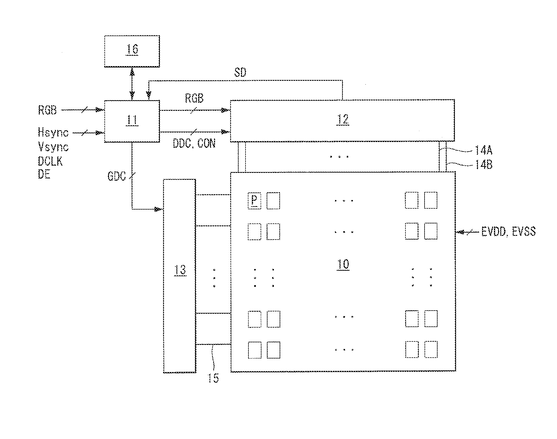
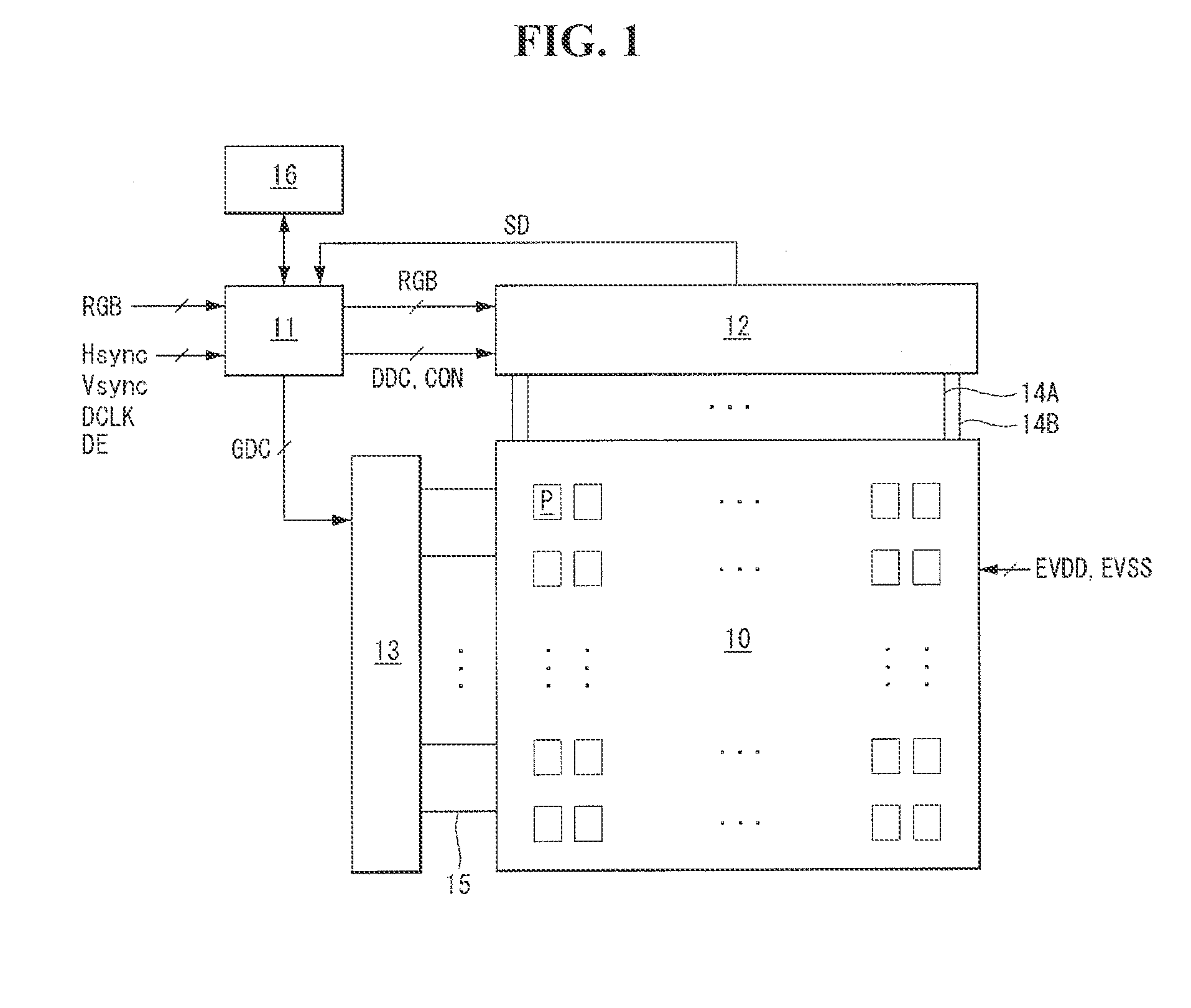
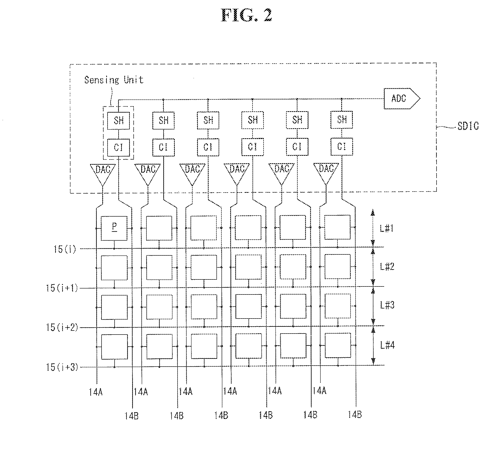
[0038]FIG. 1 is a view showing an organic light emitting display according to an exemplary embodiment of the present invention. FIG. 2 is a view showing the configuration of a pixel array formed on the display panel of FIG. 1.

[0039]Referring to FIGS. 1 and 2, the organic light emitting display according to the exemplary embodiment of the present invention comprises a display panel 10, a timing controller 11, a data driving circuit 12, a gate driving circuit 13, and a memory 16. All the components of the organic light emitting display are operatively coupled and configured

[0040]A plurality of data lines 14A and sensing lines 14B and a plurality of gate lines 15 cross over each other on the display panel 10, and pixels P are arranged in a matrix formed at their crossings.

[0041]Each pixel P is connected to any one of the data lines 14A, any one of the sensing lines 14B, and any one...


PUM


Abstract

An organic light emitting display is provided which offers shorter sensing time and higher sensing accuracy when sensing variations in electrical characteristics of a driving element. The organic light emitting display can include: a display panel with a plurality of pixels; a gate driving circuit that generates a sensing gate pulse corresponding to one line sensing ON time in a sensing operation and sequentially supplies the same to gate lines in a line sequential manner; a data driving circuit comprising a plurality of current integrators that perform an integration of the source-drain current of the driving TFT of each pixel input through the sensing lines and an ADC that sequentially digitizes the output of the current integrators to output digital sensed values; and a timing controller that controls the operations of the gate driving circuit and data driving circuit.

Description

[0001]This application claims the priority benefit of Korean Patent Application No. 10-2014-0079255 filed on Jun. 26, 2014, which is incorporated herein by reference for all purposes as if fully asset forth herein.BACKGROUND OF THE INVENTION[0002]1. Field of the Invention[0003]This document relates to an organic light emitting display, and more particularly, to an organic light emitting display which is capable of compensating for variations in electrical characteristics of a driving element.[0004]2. Discussion of the Related Art[0005]An active matrix-type organic light emitting display comprises a self-emissive organic light emitting diode (hereinafter, referred to as “OLED”), and offers advantages such as fast response speed, high light emission efficiency, high luminance, and wide viewing angle.[0006]An OLED, which is a self-emissive element, comprises an anode, a cathode, and organic compound layers HIL, HTL, EML, ETL, and EIL formed between the anode and the cathode. The organi...

Claims


Application Information

Patent Timeline
Patent Type & Authority Applications(United States)
IPC IPC(8): G09G3/32G09G3/00
CPCG09G3/3291G09G3/3258G09G3/006G09G2300/0819G09G2310/027G09G2310/08G09G2300/0828G09G2320/0223G09G2320/029G09G3/3225G09G3/3275G09G2310/0291G09G2320/045G09G2330/12G09G3/3233G09G2320/0285
Inventor KIM, TAEGUNGKIM, JUNGHYEONYOON, JINHAN
Owner LG DISPLAY CO LTD
Why Eureka
Try Eureka