Organic light emitting display for sensing electrical characteristics of driving element

a technology of driving elements and light emitting displays, which is applied in the field of organic light emitting displays, can solve the problems of difficult to realize a desired image, complex configuration of the pixel circuit, and variations from pixel to pixel, and achieve the effect of shortening the sensing time and improving the sensing performan

Active Publication Date: 2015-12-31
LG DISPLAY CO LTD
View PDF5 Cites 72 Cited by
  • Summary
  • Abstract
  • Description
  • Claims
  • Application Information

AI Technical Summary

Benefits of technology

[0016]An aspect of this document is to provide an organic light emitting display which offers shorter sensing time and higher sensing performance when sensing electrical characteristics of a driving element.

Problems solved by technology

Electrical characteristics of the driving TFT, such as threshold voltage, mobility, etc, may be deteriorated with the passage of driving time, causing variations from pixel to pixel.
This makes it difficult to realize a desired image.
The configuration of the pixel circuit is very complicated because the driving current flowing through the OLED has to be determined regardless of the threshold voltage of the driving TFTs for the sake of internal compensation.
Moreover, the internal compensation method is inappropriate to compensate for mobility variations between the driving TFTs.
First, the source voltage is sensed after the current flowing through the driving TFT is changed into the source voltage and stored by using the parasitic capacitor of the sensing line. In this case, the parasitic capacitance of the sensing line is rather large, and moreover the amount of parasitic capacitance may change with the display load of the display panel. Because parasitic capacitance is not kept at a constant level but changes due to a variety of environmental factors, it cannot be calibrated. Any change in the amount of parasitic capacitance where current is stored makes it difficult to obtain an accurate sensed value.
Second, it takes quite a long time to obtain a sensed value, for example, until the source voltage of the driving TFT is saturated, because the conventional external compensation method employs voltage sensing. Especially, if the parasitic capacitance of the sensing line is large, it takes much time to draw enough current to meet a voltage level at which sensing is enabled. This problem becomes more serious in the case of low-grayscale sensing than in the case of high-grayscale sensing, as shown in FIG. 1.

Method used


Image

  • Organic light emitting display for sensing electrical characteristics of driving element
  • Organic light emitting display for sensing electrical characteristics of driving element
  • Organic light emitting display for sensing electrical characteristics of driving element

Examples


Embodiment Construction

[0046]Hereinafter, exemplary embodiments of the present invention will be described with reference to the accompanying drawings. In the following description, detailed descriptions of related well-known functions or configurations will be omitted if they would obscure the invention with unnecessary detail.

1. Current Sensing Method

[0047]A current sensing method on which the present invention is based will be explained.

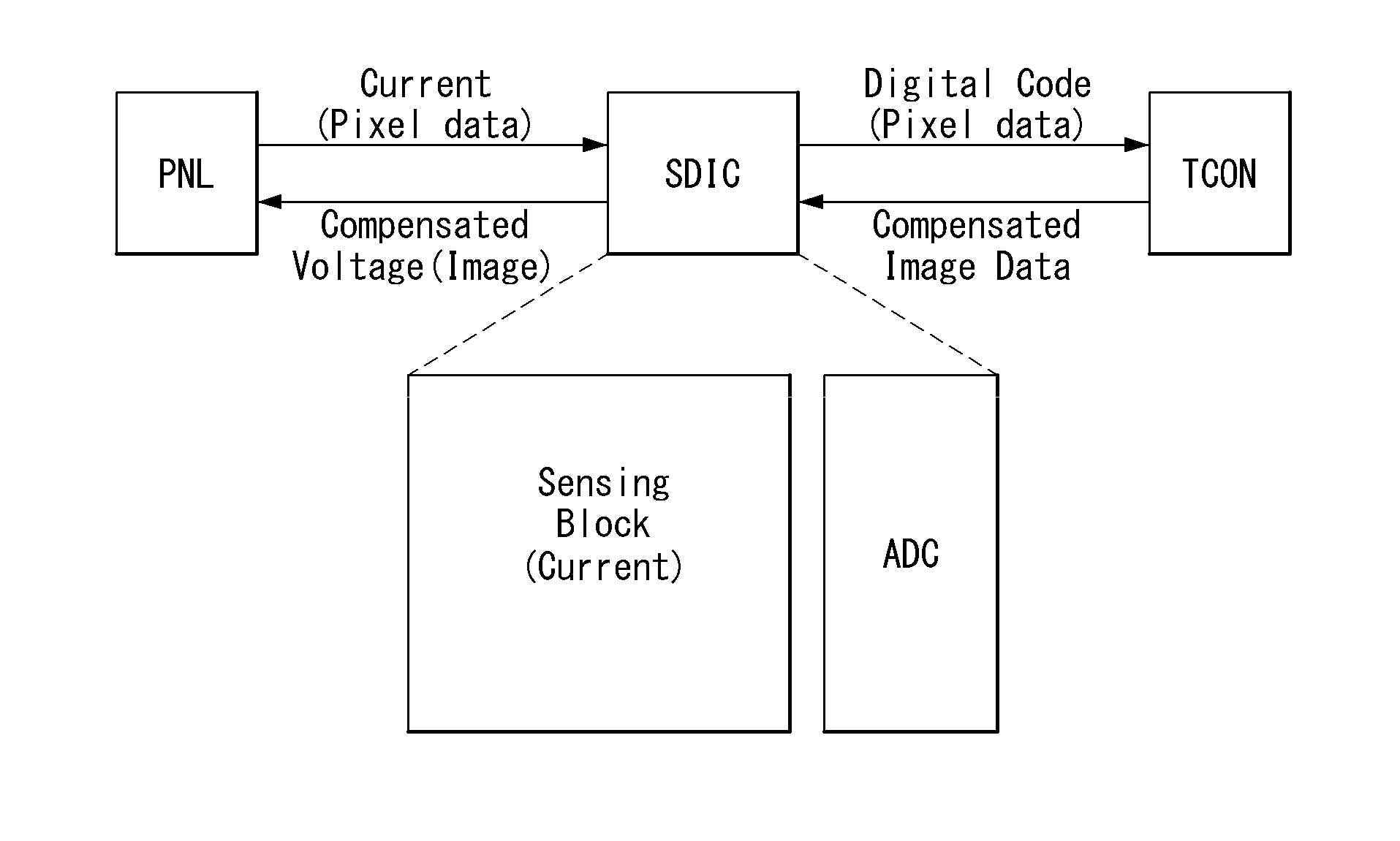
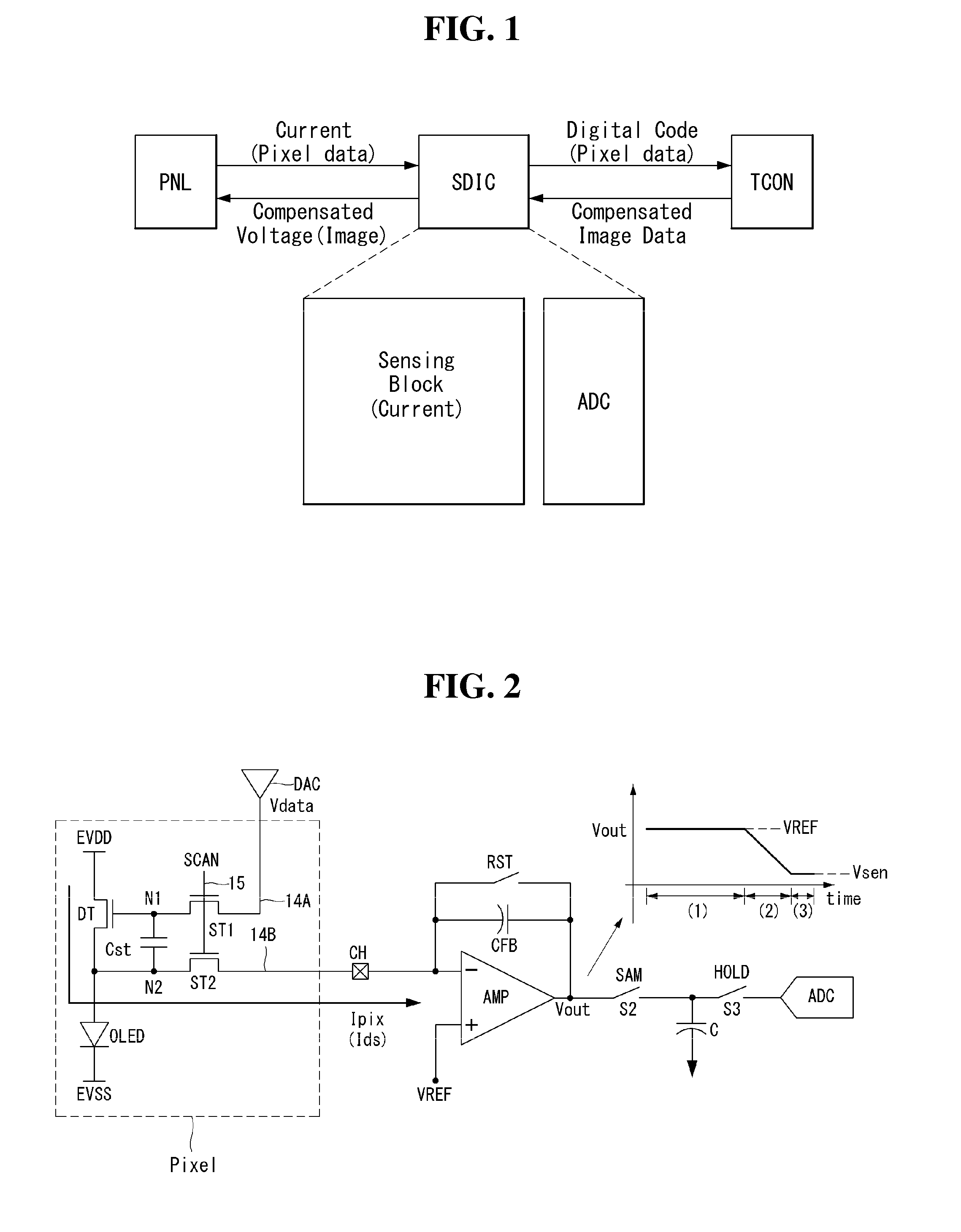
[0048]FIG. 1 shows a schematic configuration of an organic light emitting display which implements external compensation based on a current sensing method. FIG. 2 shows a connection structure between one pixel and a current integrator which is applied to external compensation using the current sensing method.

[0049]Referring to FIG. 1, in the present invention, a sensing block and an ADC (analog-to-digital converter), which are required for current sensing, are included in a data driver IC SDIC, and current data is sensed from the pixels of a display panel. The sensing b...


PUM


Abstract

An organic light emitting display comprises: a display panel with a plurality of pixels connected to data lines and sensing lines, each pixel comprising an OLED and a driving TFT for controlling the amount of light emission of the OLED; and a data driver IC comprising a plurality of sensing units for sensing current data of the pixels through a plurality of sensing channels connected to the sensing lines, each sensing unit comprising: a first current integrator connected to an odd sensing channel; a second current integrator connected to an even sensing channel neighboring the odd sensing channel; and a sample & hold unit that removes common noise components from a first sampled value input from the first current integrator and a second sampled value input from the second current integrator while storing and holding the first and second sampled values.

Description

[0001]This application claims the benefit of Korean Patent Application No. 10-2014-0080000 filed on Jun. 27, 2014, which is incorporated herein by reference for all purposes as if fully forth herein.BACKGROUND OF THE INVENTION[0002]1. Field of the Invention[0003]This document relates to an organic light emitting display. More particularly, the document relates to an organic light emitting display which is capable of sensing electrical characteristics of a driving element.[0004]2. Discussion of the Related Art[0005]An active matrix-type organic light emitting display comprises a self-emissive organic light emitting diode (hereinafter, referred to as “OLED”), and offers advantages such as fast response speed, high light emission efficiency, high luminance, and wide viewing angle.[0006]An OLED, which is a self-emissive element, comprises an anode, a cathode, and organic compound layers HIL, HTL, EML, ETL, and EIL formed between the anode and the cathode. The organic compound layers com...

Claims


Application Information

Patent Timeline
Patent Type & Authority Applications(United States)
IPC IPC(8): G09G3/00G09G3/32
CPCG09G3/006G09G3/3291G09G3/3258G09G2310/027G09G2330/12G09G2300/0819G09G2320/045G09G2320/0693G09G3/2007G09G2300/0426G09G2300/0828G09G2320/0295
Inventor YU, SANGHOKIM, BUMSIK
Owner LG DISPLAY CO LTD
Why Eureka
Try Eureka