Display device with a backlight

a backlight and display device technology, applied in the field of display devices, can solve the problems of large power requirement of this configuration, outweigh the advantage of high-color display, and less efficient than using w leds, and achieve the effect of minimal power requiremen

Active Publication Date: 2015-12-31
SHARP KK
View PDF0 Cites 4 Cited by
  • Summary
  • Abstract
  • Description
  • Claims
  • Application Information

AI Technical Summary

Benefits of technology

[0009]In conventional display devices there does not exist any display comprising independently controllable R, G, B and W light emitting devices, and also having a method for selecting the optimum drive currents for each emitter in the backlight such that image content can be faithfully displayed, either to an intended standard color space, or to the maximum achievable gamut of the display, with a minimal power requirement. The present invention provides a complete system in which, for every image to be displayed on the display, the image data is analyzed, the optimal backlighting conditions are calculated and applied, and the image data is converted to be displayed accurately given the new light spectrum emitted from the backlight.

Problems solved by technology

However, the power requirement of this configuration is large, and outweighs the advantage of the high-color display.
However, this still requires the RGB LEDs to be used even for pale colors, which is less efficient than using W LEDs.
In this way they reduce the power consumption of the backlight device, but they also restrict the vividness of the image data to be displayed.
This clearly reduces the vividness of the color that the panel can produce, even though the image content might require high saturation levels.
However, this gives a non-uniform distribution of brightnesses, contrary to standardized color spaces.

Method used


Image

  • Display device with a backlight
  • Display device with a backlight
  • Display device with a backlight

Examples


Embodiment Construction

[0057]In a first embodiment, a display device includes an LC display, with modified control electronics and backlight emitters. An LCD display generally has several component parts including:

[0058]1. A backlighting unit to supply even, wide angle illumination to the panel.

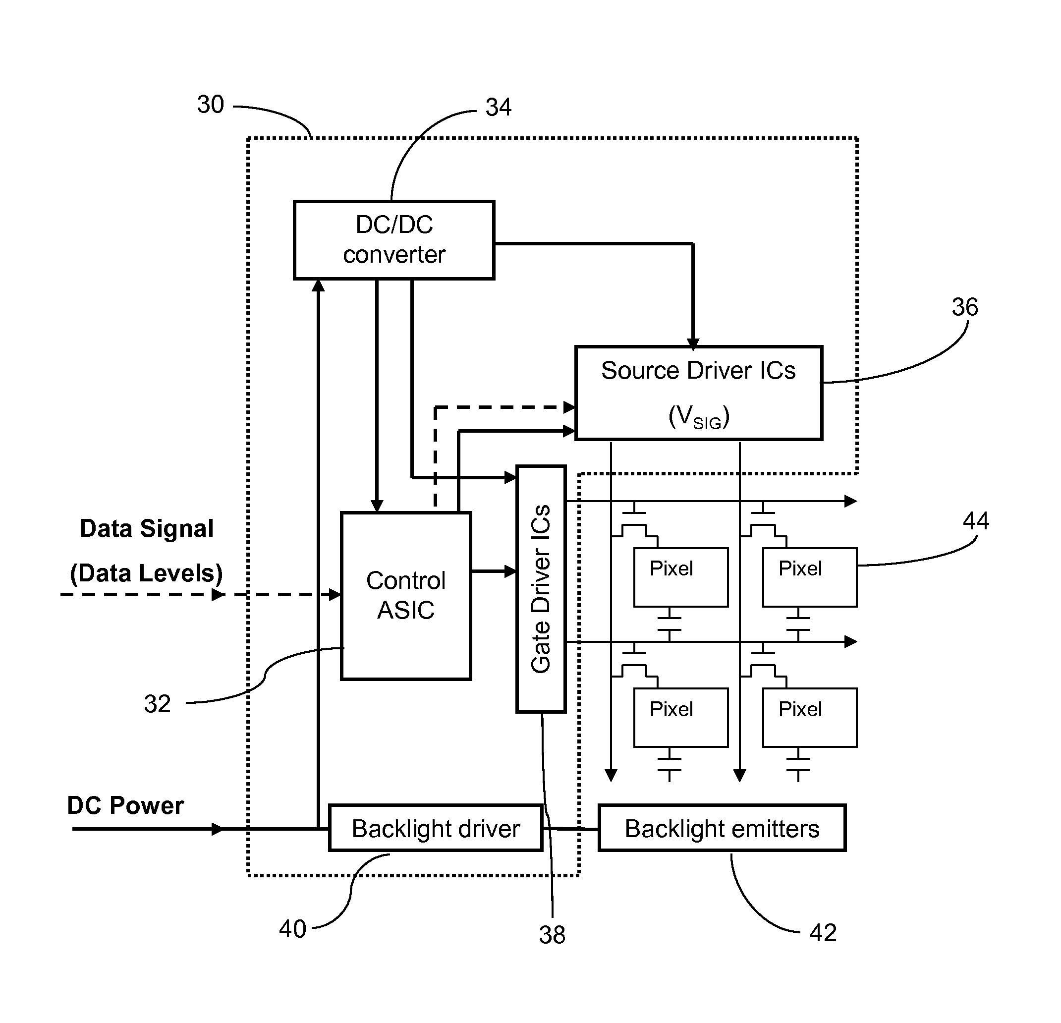
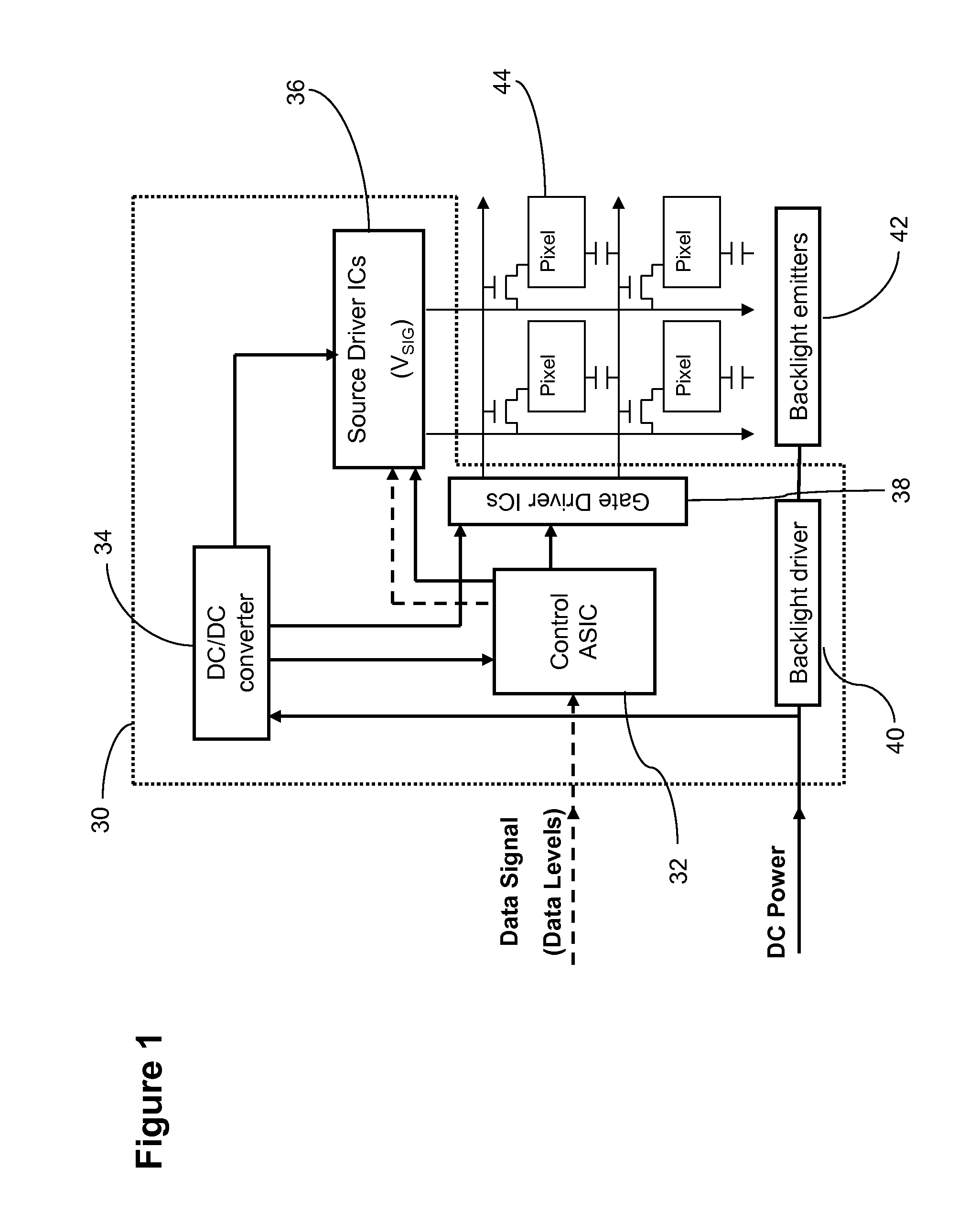
[0059]2. Control electronics to receive digital image data and output analogue signal voltages for each pixel, as well as timing pulses and a common voltage for the counter electrode of all pixels. A schematic of the standard layout of LCD control electronics is shown in FIG. 1 (adapted from Ilias Pappas, Stylianos Siskos and Charalambos A. Dimitriadis (2009). Active-Matrix Liquid Crystal Displays—Operation, Electronics and Analog Circuits Design, New Developments in Liquid Crystals, Georgiy V Tkachenko (Ed.), ISBN: 978-953-307-015-5, InTech, DOI: 10.5772 / 9686).

[0060]As seen in FIG. 1, control electronics 30 include a control ASIC 32 that receives data signals from a data line. The control ASIC 32 is configured wit...


PUM

PropertyMeasurementUnit
thicknessaaaaaaaaaa
broader spectrumaaaaaaaaaa
color renderingaaaaaaaaaa

Abstract

A display includes a backlight portion having at least one broad spectrum emitter (such as white) and at least one narrow spectrum emitter (such as red, green, and blue), a liquid crystal panel for displaying an image by spatial light modulation, and control electronics configured to receive input image data and output control signals to both the backlight portion and liquid crystal panel. The control electronics is configured to use color rendering capabilities of the liquid crystal panel under illumination from each of the emitter types individually to calculate a minimum power combination of emission from each emitter type required to display the input image data. The control electronics is further configured to modify the input image data according to the calculated minimum power combination of emitter powers so a resulting display of colours in the image data remains despite changing illumination conditions.

Description

TECHNICAL FIELD[0001]The invention relates to a display device and, more particularly, to a display device comprising a combination of backlight emitters, and a means of selectively powering each backlight at different levels, and a means of modifying the image data input to the display so as to maintain correct color appearance under the different possible backlight emitter levels.BACKGROUND ART[0002]In an active matrix liquid crystal display (LCD), an image is produced by controlling the light transmittance of a two-dimensional array of discrete image elements (subpixels). Control is performed by the conversion of digital image data, consisting of a data value for each subpixel of the image, into analogue voltages with values dependent on that data, and direction of those voltages to each pixel electrode in the array via an active matrix of source data lines, gate lines and thin film transistor (TFT) switching elements.[0003]A block of three subpixels is termed a pixel. Each subpi...

Claims


Application Information

Patent Timeline
Patent Type & Authority Applications(United States)
IPC IPC(8): G09G5/10G09G5/18G09G5/02G02F1/1335G09G3/36
CPCG02F1/133603G09G2340/06G09G2310/0235G09G3/3413
Inventor HEYWOOD-LONSDALE, EDWARD DAVIDBROUGHTON, BENJAMIN JOHNWALTON, EMMA JAYNENONWEILER, JOHN PATRICKSEKI, FUMITAKA
Owner SHARP KK
Why Eureka
Try Eureka