X-ray apparatus with deflectable electron beam

a technology of electron beam and x-ray apparatus, which is applied in the direction of x-ray tube electrodes, cathode ray concentrating/focusing/directing, x-ray tube target materials, etc., can solve the problems of difficult mechanically moving the x-ray optics in the m range to match the focal spot of the x-ray source with the focus of the x-ray optics in practice, and achieve the effect of maximizing the photon flux, maximizing

Active Publication Date: 2015-12-31
BRUKER AXS
View PDF9 Cites 7 Cited by
  • Summary
  • Abstract
  • Description
  • Claims
  • Application Information

AI Technical Summary

Benefits of technology

[0017]By means of the electron beam deflection device, the focal spot can be moved on the target. The X-ray apparatus is aligned when the focal spot of the electron beam on the target overlaps the focus of the x-ray optics. Instead of mechanically moving the X-ray optics, the inventive apparatus allows moving the focal spot, what can conveniently be done with electric means (such as changing the voltage between electrodes or changing an electric current through an electromagnetic coil), in particular without using alignment mechanics. An electric alignment is highly reproducible, allows a higher precision, and is in particular not subject to backlash effects. Accordingly, the inventive apparatus can be aligned in a fast and simple way.
[0043]In an advantageous further development, the target of the apparatus is chosen as a target with a curved surface having a radius of curvature R, with 0<R 5≦1 mm. This simplifies changing the operation modes by moving the focal spot on the target.

Problems solved by technology

However, mechanically moving the X-ray optics on the μm range to match the focal spot of the X-ray source with the focus of the X-ray optics is difficult in practice, in particular due to backlash of alignment mechanics.

Method used


Image

  • X-ray apparatus with deflectable electron beam
  • X-ray apparatus with deflectable electron beam
  • X-ray apparatus with deflectable electron beam

Examples


Embodiment Construction

Overview of the Invention

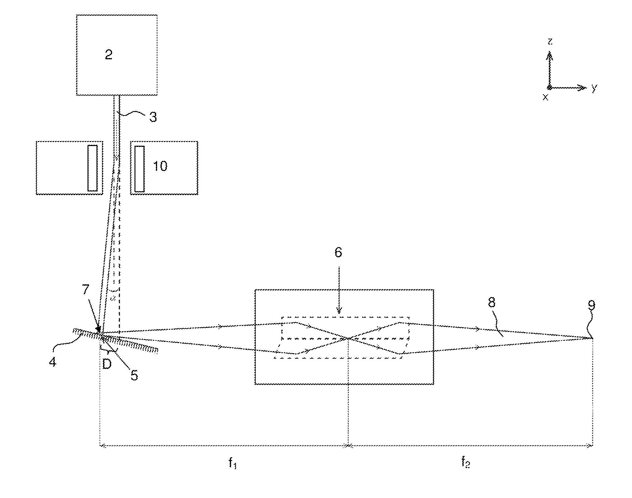
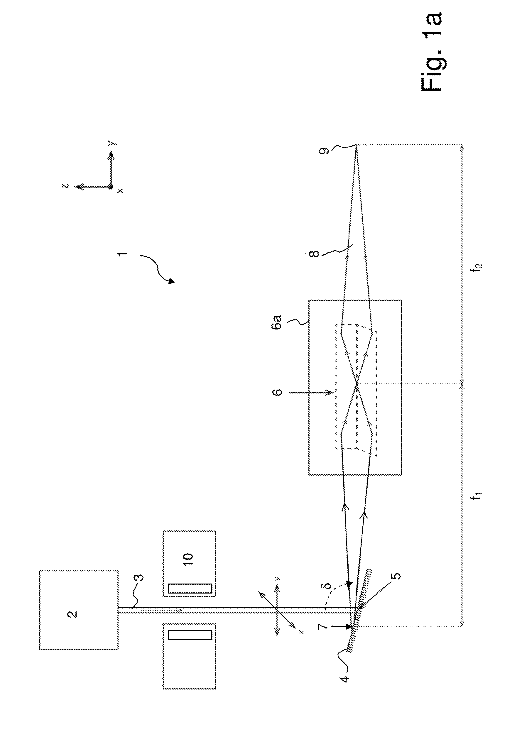
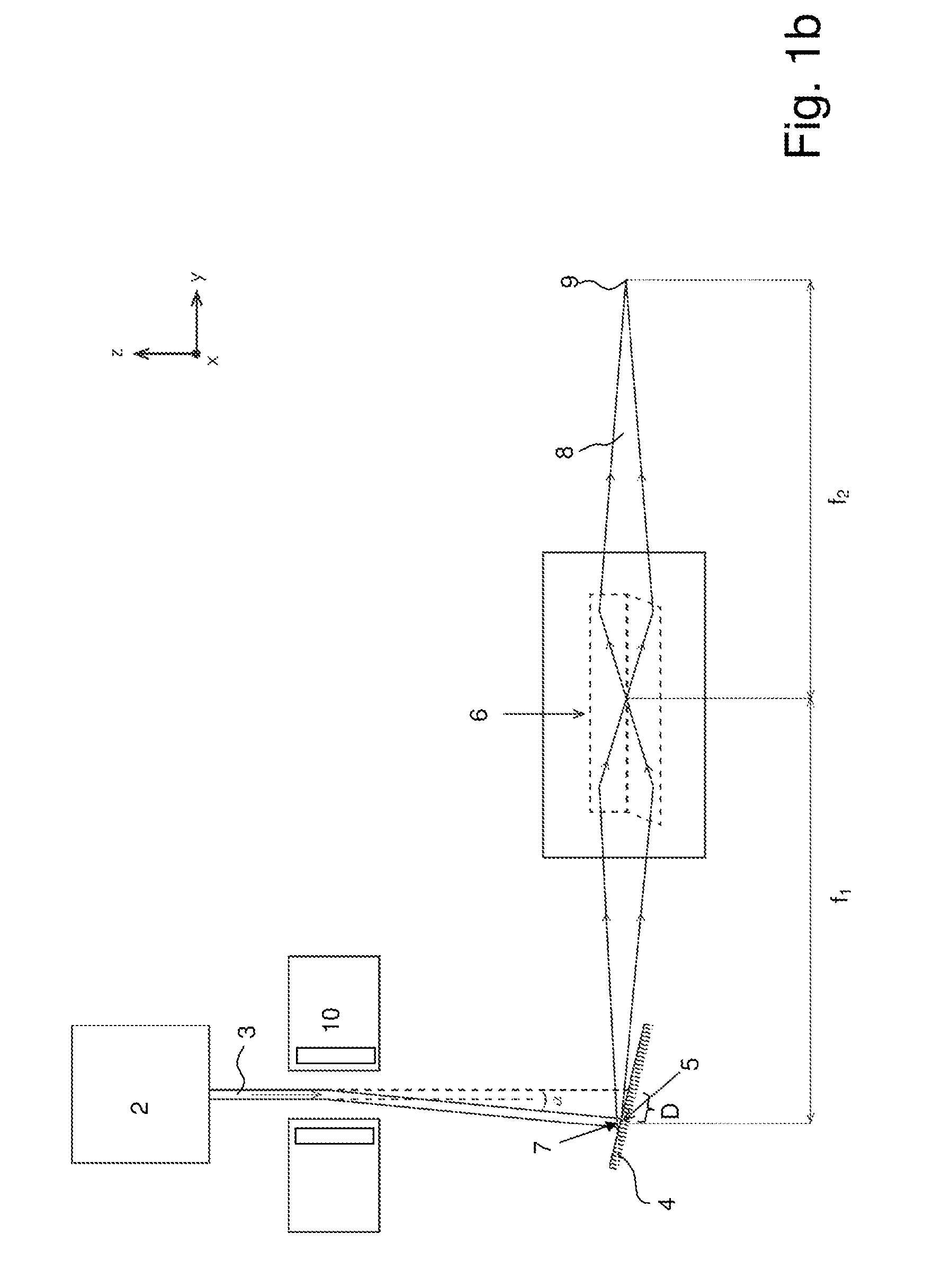
[0059]The invention proposes an X-ray apparatus with an X-ray source, in particular a microfocus X-ray source, which allows for a continuous variation of the position of the electron beam on the target, in particular a liquid metal jet target, preferably in two directions. In other words, the position of the focal spot of the electron beam is variable. To alter the spot position, the electron beam can be deflected by applying an electric and / or magnetic field to the electron beam.

[0060]As an advantage of the variable spot position, it is possible to align the X-ray source and a subsequent X-ray optics in a fast and comfortable way. In the state of the art, the alignment is done only mechanically. Due to the backlash of the mechanics in and / or at the optics housing it is difficult and time consuming to optimize the alignment (which is done by increasing the photon flux of the primary beam). However, by varying the spot position on the target, the relative pos...


PUM


Abstract

An x-ray apparatus (1), has an electron beam source (2), a target (4), onto which the electron beam (3) is directed to form a focal spot (5; 5a, 5b) on the target (4), x-ray optics (6) for collecting x-rays emitted from the focal spot (5; 5a, 5b) to form an x-ray beam (8) and a sample position (9) at which the x-ray beam (8) is directed. The x-ray apparatus (1) further includes an electrostatic or electromagnetic electron beam deflection device (10) suitable for moving the focal spot (5; 5a, 5b) on the target (4). The extension of the focal spot (5; 5a, 5b) in any direction (x, y, z) is at least a factor of 1.5 smaller than the extension of the target (4). An x-ray apparatus is thereby provided with simplified alignment of the x-ray optics with respect to a microfocus x-ray source.

Description

[0001]This application is a continuation of Ser. No. 13 / 706,374 filed Dec. 6, 2012 the entire disclosure of which is hereby incorporated by reference.BACKGROUND OF THE INVENTION[0002]The invention relates to an X-ray apparatus, comprising[0003]an electron beam source, emitting an electron beam,[0004]a target, onto which the electron beam is directed, thus forming a focal spot on the target,[0005]X-ray optics, collecting X-rays emitted from the focal spot and forming an X-ray beam,[0006]and a sample position at which the X-ray beam is directed.[0007]Such an X-ray apparatus is known from U.S. Pat. No. 7,929,667 B1.[0008]By means of X-rays, samples may be investigated in a destruction-free and efficient manner. X-rays may interact with a sample in numerous ways in order to obtain analytical information about the sample, with X-ray diffraction (XRD) and X-ray fluorescence (XRF) being two important methods. In general, high X-ray intensities are useful to obtain high signal to noise rati...

Claims


Application Information

Patent Timeline
Patent Type & Authority Applications(United States)
IPC IPC(8): H01J35/30H01J35/14H05G1/58H01J35/08
CPCG21K1/067G21K1/06H01J35/08H05G1/58H01J2235/082H01J2235/086H01J35/14H01J35/30H01J35/112H01J35/147H01J35/153
Inventor OLLINGER, CHRISTOPHMICHAELSEN, CARSTENKLEINE, ANDREASGRAF, JUERGEN
Owner BRUKER AXS
Why Eureka
Try Eureka