Tray for a wafer with tape frame

a technology of tape frame and wafer, which is applied in the field of tape frame, can solve the problems of insufficient to prevent etc., and achieve the effects of reducing the swing preventing the breakage and avoiding transcription and scratches to the surface of the semiconductor wafer

Active Publication Date: 2015-12-31
ACHILLES CORP
View PDF10 Cites 5 Cited by
  • Summary
  • Abstract
  • Description
  • Claims
  • Application Information

AI Technical Summary

Benefits of technology

[0014]In a tray which is used when a wafer with tape frame is stored in a storage container according to the present invention, it is possible to reduce swings of a semiconductor wafer by vibrations of the container even when the wafer with tape frame includes an ultrathin semiconductor wafer having a thickness of 200 μm or less and it is transported by being stored in the container. It is possible to certainly prevent breakage of the semiconductor wafer by avoiding transcriptions and scratches to the surface of the semiconductor wafer even when a semiconductor wafe

Problems solved by technology

In a container described in Patent Document 1, swings of semiconductor wafers by vibrations of a container become large during transportation of wafers with tape frame stored in a container when the thickness of semiconductor wafers becomes 200 μm or less, and as a result, it causes a problem of breaking the semicondu

Method used


Image

  • Tray for a wafer with tape frame
  • Tray for a wafer with tape frame
  • Tray for a wafer with tape frame

Examples


embodiment

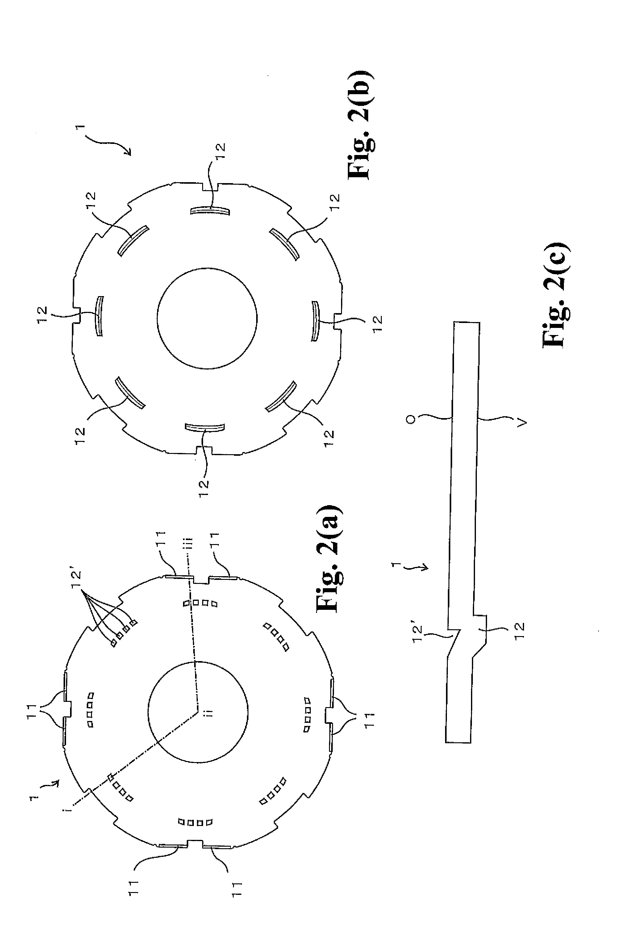
[0073][Production of a Tray]

[0074]A tray having a shape shown in FIG. 2 (Embodiment 1) and a tray having a shape shown in FIG. 3 (Embodiment 2) were obtained by injection molding of polycarbonate resin containing carbon fiber (“Panlite B-7115R” made by Teijin Chemicals Ltd.: the content ratio of carbon fiber is about 15%). The surface resistances of the obtained trays were in a range between 102Ω and 105Ω.

[0075]Drop tests and transcription tests were performed for the obtained trays according to Embodiments 1 and 2. The test methods were as follows.

[0076][Drop Test]

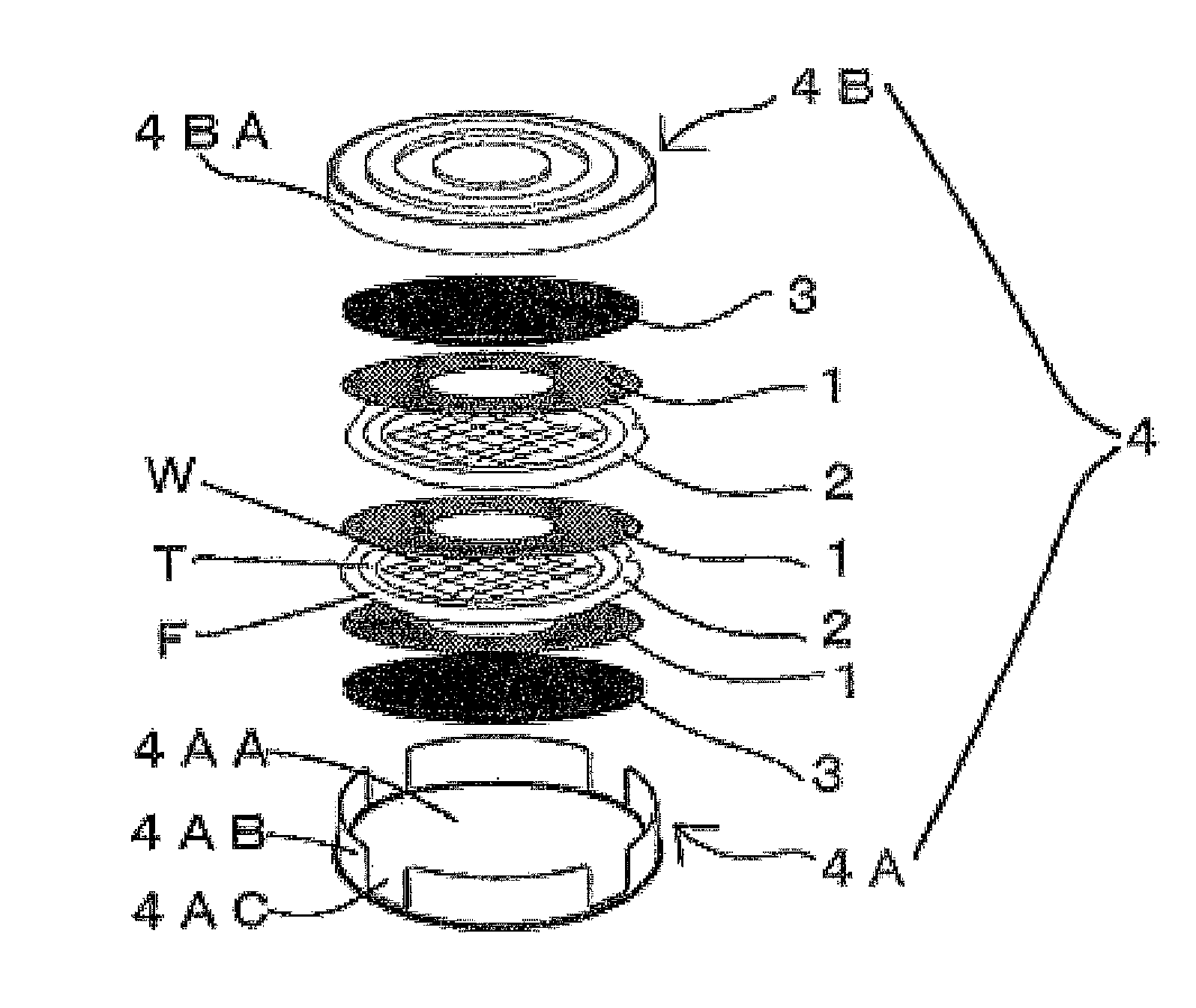
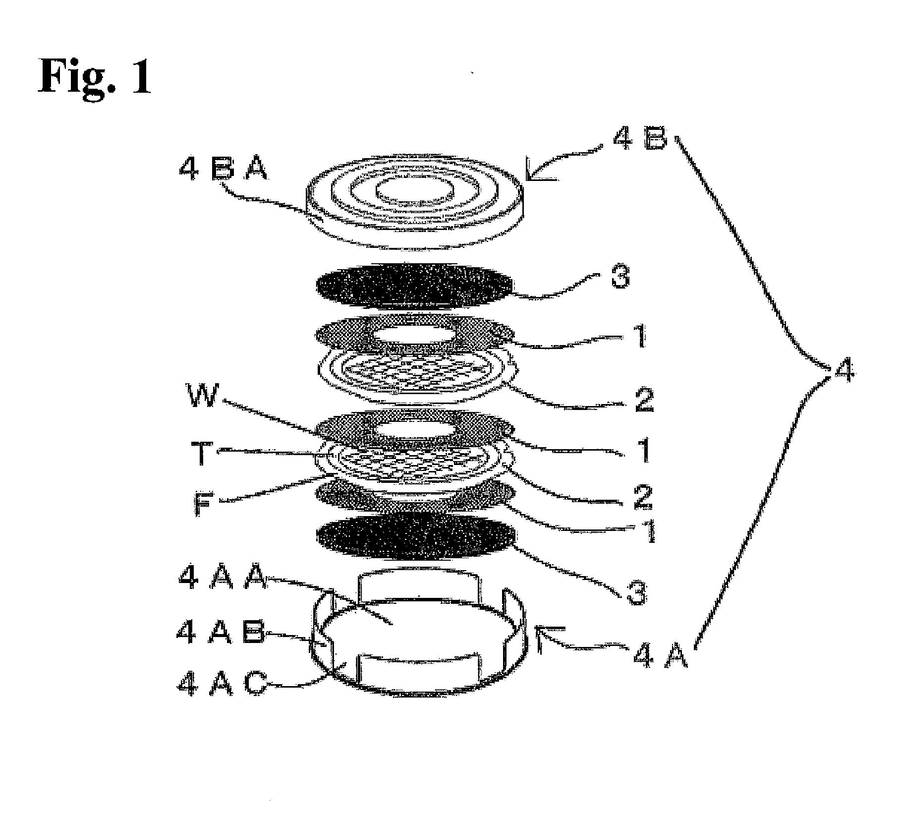
[0077]A storage container 4 (a columnar shaped storage container of 430 mm in outer diameter×74 mm in height) was prepared by storing a cushion member 3, a tray 1, a wafer with tape frame 2, a tray 1, and then a stack of a wafer with tape frame 2 and a tray 1 repeatedly in the container body 4A shown in FIG. 1, and putting a cushion member 3 on the topmost tray 1, and attaching the cover body 4B to the container body 4A....


PUM


Abstract

A tray for storing a wafer with a tape frame in a storage container includes a ring-shaped frame, a dicing tape and a semiconductor wafer. The dicing tape is stuck on the rear surface of the ring-shaped frame, and the semiconductor wafer is supported on the dicing tape. The tray has a substantially circular shape and is positioned on the upper side and the lower side of the wafer with tape frame. The front surface of the tray has a flat portion for mounting the wafer, and at least a portion of the outer peripheral portion of the front surface of the tray includes a convex portion. A projecting portion is formed on the rear surface so that the projection portion is positioned outside the outer periphery of the semiconductor wafer of the wafer with the tape frame when the tray is positioned on the wafer with tape frame.

Description

TECHNICAL FIELD[0001]The present invention relates to a tray used for storing a wafer with tape frame in a storage container.BACKGROUND ART [0002]Conventionally, a wafer with tape frame is formed by sticking a dicing tape on a ring-shaped frame and supporting a semiconductor wafer on the dicing tape, and the wafer with tape frame is stored in a storage container and transported to a dicing process and a die bonding process.[0003]As a container for storing a wafer with tape frame, it is known to use a horizontal (a coin stuck type) transport container for storing a semiconductor wafer in a horizontal direction as shown in Patent Document 1, for example. More specifically, it is a container for stacking and storing two or more stages of frames with tape frame, which comprises a container body having a storage cylindrical portion for storing the stacked wafers with tape frame and a cover body for covering the entire storage cylindrical portion by attaching to the container body in a de...

Claims


Application Information

Patent Timeline
IPC IPC(8): H01L21/683
CPCH01L21/67346H01L21/6836H01L2221/68327
Inventor NISHIJIMA, MASAYUKI
Owner ACHILLES CORP
Why Eureka
Try Eureka