Wavelength conversion element, light source device, and projector

a technology of light source device and wavelength conversion layer, which is applied in the direction of picture reproducers using projection devices, lighting and heating apparatus, instruments, etc., can solve the problems of degradation of the conversion efficiency of phosphor and breakage of phosphor, and achieve the effect of inhibiting the wavelength conversion layer from rising in temperature to a high temperature level

Active Publication Date: 2015-12-31
SEIKO EPSON CORP
View PDF1 Cites 14 Cited by
  • Summary
  • Abstract
  • Description
  • Claims
  • Application Information

AI Technical Summary

Benefits of technology

[0028]According to the aspect of the projector according to the invention, since any one of the light source devices described...

Problems solved by technology

If the temperature of the phosphor becomes high, there has been a possibility of cau...

Method used


Image

  • Wavelength conversion element, light source device, and projector
  • Wavelength conversion element, light source device, and projector
  • Wavelength conversion element, light source device, and projector

Examples


specific example

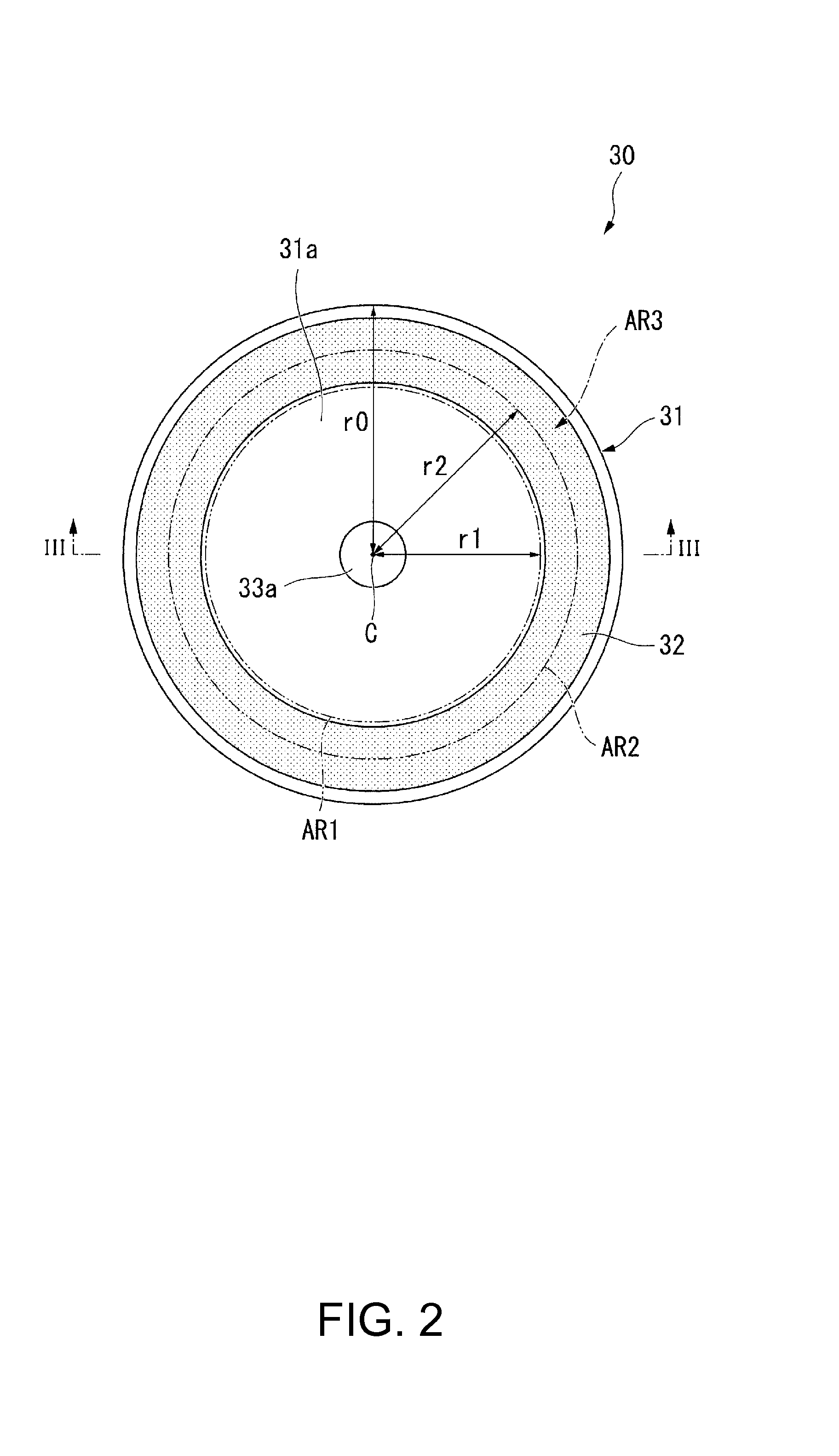
[0126]In the present specific example, the variation of the thermal resistance ρ of the wavelength conversion element with respect to the moving radius r was obtained by a simulation.

[0127]The thermal resistance ρs of the disk can be obtained from the temperature distribution of the disk. Assuming that the heat generation amount of the heat generation region is Ww, the average temperature of the disk is Tave, and the temperature of the heat generation region is Tmax, the thermal resistance ρs of the disk can be provided by Formula 4.

ρs=(Tmax−Tave) / Ww  Formula 4

[0128]In the simulation, the radius r0 of the disk, the thickness Ts of the disk, the thermal conductivity λs of the disk, the heat-transfer coefficient h from the disk to the air, the heat generation amount Ww of the heat generation region, and the moving radius r of the heat generation region were used as parameters. Specifically, r0=60 (mm), Ts=1 (mm), h=72 (w / (m2K)), and Ww=1 (W) were used. Further, a ring centered on the ...


PUM


Abstract

A wavelength conversion element includes a disk, a wavelength conversion layer disposed above a first surface of the disk, and a reflecting layer disposed between the disk and the wavelength conversion layer, and Formula 1 is fulfilled.
dρw(r0)/dr<dρs(r0)/dr  (Formula 1)
    • where, assuming that a circular polar coordinate system having the rotational center as an origin is set on a plane parallel to the first surface of the disk,
    • r: moving radius in the circular polar coordinate system,
    • r0: radius of the disk,
    • ρs(r): thermal resistance of thermal paths passing through inside and a surface of the disk between a point with the moving radius r on the first surface of the disk and an entire surface of the disk, and
    • ρw(r): thermal resistance of the wavelength conversion layer in a thickness direction of the wavelength conversion layer at the moving radius r.

Description

BACKGROUND[0001]1. Technical Field[0002]The present invention relates to a wavelength conversion element, a light source device, and a projector.[0003]2. Related Art[0004]As described in, for example, JP-A-2009-277516, there has been proposed a light source device having a configuration in which a layer of phosphor for emitting light in response to reception of excitation light is disposed on a transparent member having a circular shape, and the transparent member is rotated by an electric motor.[0005]In such a light source device as described above, if the excitation light is intensified, the amount of heat generation in the phosphor, namely a wavelength conversion layer, increases, and thus the temperature of the phosphor rises. If the temperature of the phosphor becomes high, there has been a possibility of causing degradation of the conversion efficiency of the phosphor and breakage of the phosphor.SUMMARY[0006]An advantage of some aspects of the invention is to provide a wavele...

Claims


Application Information

Patent Timeline
IPC IPC(8): H04N9/31F21V14/08G02B26/00
CPCH04N9/3144G02B26/008G03B21/142H04N9/3111H04N9/3158
Inventor EGAWA, AKIRA
Owner SEIKO EPSON CORP
Why Eureka
Try Eureka