Primed Jet Toilet

Active Publication Date: 2016-01-07
AS AMERICA
View PDF1 Cites 20 Cited by
  • Summary
  • Abstract
  • Description
  • Claims
  • Application Information

AI Technical Summary

Benefits of technology

[0022]Included within the scope of the invention is a siphonic flush toilet bowl assembly, comprising at least one jet flush valve assembly having a jet flush valve inlet and a jet flush valve outlet, the jet flush valve assembly configured for delivery of fluid from the jet flush valve outlet to a closed jet fluid pathway; at least one rim valve having a rim valve inlet and a rim valve outlet, the rim valve configured for delivery of fluid from the outlet of the rim valve to a rim inlet port; and a bowl having an interior surface defining an interior bowl area and comprising (a) at least one rim inlet port for introducing water to an upper perimeter area of the bowl; (b) a jet defining at least one jet channel, the jet having an inlet port in fluid co

Problems solved by technology

This causes a rapid rise in water level and the excess water spills over the weir of the trapway, carrying liquid and solid waste along with it.
Siphonic toilets, due to the requirement that most of the air be removed from the down leg of the trapway in order to initiate a siphon, tend to have smaller trapways which can result in clogging.
Wash-down toilets with their small water spots therefore frequently require manual cleaning of the bowl after use.
Non-jetted bowls typically have adequate to good performance with respect to cleansing of the bowl and exchange of the pre-flush water, but are relatively poor in performance in terms of bulk removal.
The feed of water to the trapway is inefficient and turbulent, which makes it more difficult to sufficiently fill the down leg of the trapway and initiate a strong siphon.
Without the smaller size, bends, and constrictions, a strong siphon would not be achieved.
U

Method used


Image

  • Primed Jet Toilet
  • Primed Jet Toilet
  • Primed Jet Toilet

Examples


example

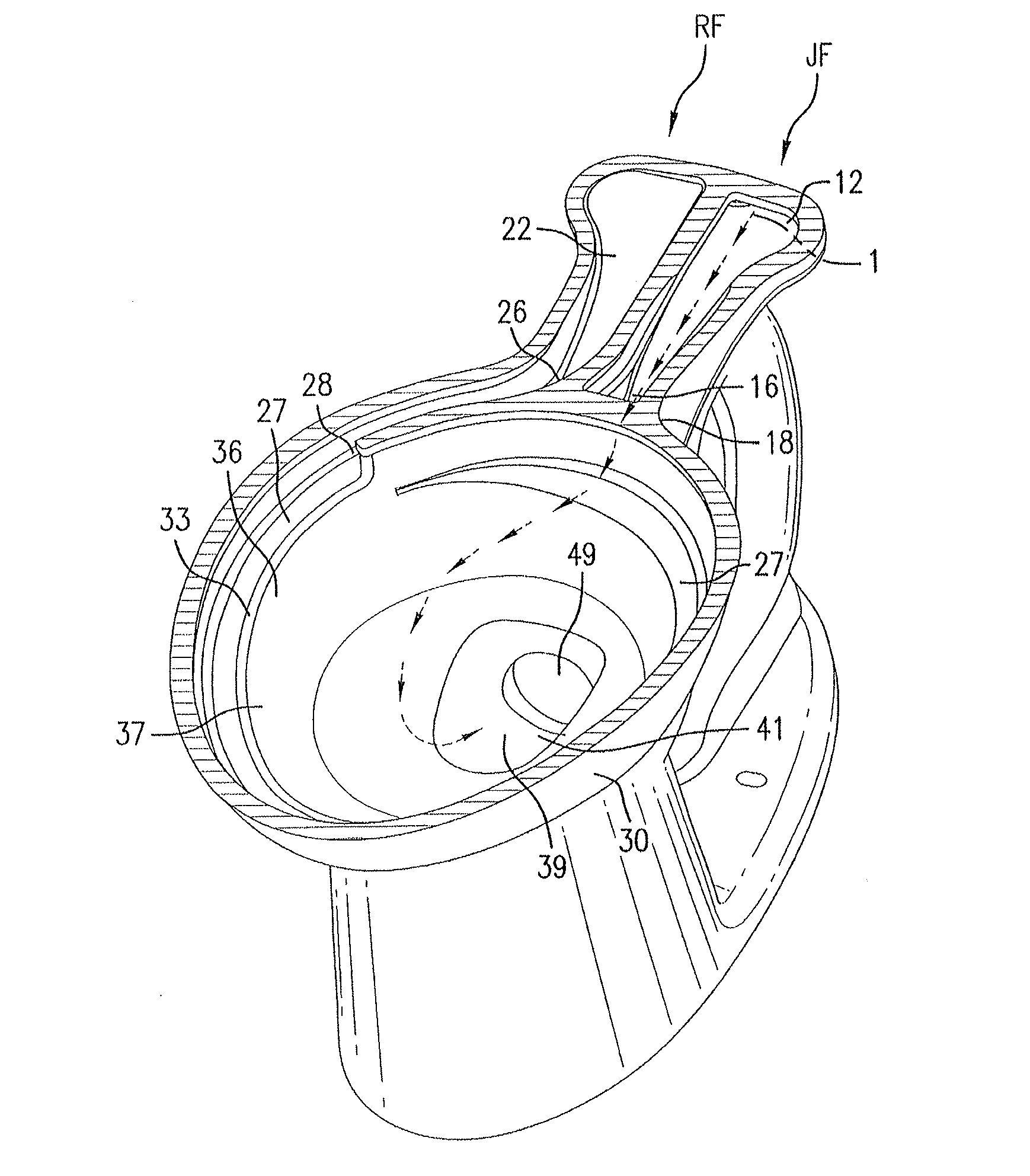
[0276]Table 1 summarizes data from 20 flushes completed using three different toilets. The present invention was tested based on the embodiment shown herein in FIGS. 1-13 and 29-34. Prior art toilets tested required 79-82% of the flush water to be directed to the jet to achieve desired hydraulic performance of the siphon. The toilet made according to the present invention provided essentially equivalent hydraulic performance using less than 30% of the flush water directed to the jet, thereby allowing the remainder of the water to be used for significant improvement to bowl cleaning.

TABLE 1MainPeakTime toTime toFlushRatePeak2500 ml / s[l][l / s][s][s]Prior Art Toilet “K”Average4.3433.2390.7780.40579% of Main FlushSTD0.0680.1160.1440.03Volume Through JetMAX4.4583.4780.990.45MIN4.2192.9940.550.35Prior Art Toilet “T”Average4.3673.940.60.32282% of Main FlushSTD0.1860.1120.0390.016Volume Through JetMAX4.8294.1750.690.36MIN4.1063.7620.540.3Present InventionAverage4.4563.5470.9820.58327% of Mai...


PUM


Abstract

A siphonic flush toilet system and method of priming the same having a toilet bowl assembly comprising at least one jet flush valve assembly and at least one rim valve; and bowl having a rim and a jet defining at least one jet channel. The bowl has a closed jet pathway to maintain the jet channel in a primed state with fluid from the jet flush valve assembly to prevent air from entering the closed jet pathway. Flush valves may have back-flow preventer mechanisms and/or at least partly flexible valve covers, including specific valve cover structures. Flush activation assemblies may have a flush activation bar connected to the pivot rod and/or an adjustable flush connector located between the pivot rod and the flush activation bar. A kit providing one or more flush activation elements is included. The kit elements may be usable with the toilet systems and methods described.

Description

CROSS-REFERENCE TO RELATED APPLICATIONS[0001]This application claims the benefit under 35 U.S.C. §119(e) of U.S. Provisional Patent Application No. 62 / 049,736 filed Sep. 12, 2014, entitled “Primed Jet Toilet” and also claims priority as a continuation-in-part of U.S. Non-Provisional patent application Ser. No. 14 / 619,989 filed on Feb. 11, 2015 under 35 U.S.C. §120 entitled, “Primed Siphonic Flush Toilet,” which claims priority under 35 U.S.C. §120 as a continuation of International Patent Application No. PCT / US2013 / 069961, filed Nov. 13, 2013, under 35 U.S.C. §120, published in English, which claims the benefit under 35 U.S.C. §119(e) of U.S. Provisional Patent Application No. 61 / 810,664, filed Apr. 10, 2013, entitled, “Primed Siphonic Flush Toilet” and of U.S. Provisional Patent Application No. 61 / 725,832, filed Nov. 13, 2012, entitled, “Primed Siphonic Flush Toilet.” The entire disclosures of the above-noted applications are incorporated herein by reference in their entirety.BACKG...

Claims


Application Information

Patent Timeline
IPC IPC(8): E03D5/02E03D1/34E03D11/08
CPCE03D1/34E03D5/02E03D11/08E03D11/06E03D1/145E03D1/306E03D2201/30E03D2201/40
Inventor GROVER, DAVIDISHIYAMA, DAIGOBUCHER, CHRISTOPHELE, TUANMCHALE, JAMES
Owner AS AMERICA
Why Eureka
Try Eureka