Removing non-homogeneous ice from a fuel system

a fuel system and non-homogeneous technology, applied in the field of fuel systems, can solve the problems of affecting the performance of the engine, the formation of ice in the liquid fuel,

Active Publication Date: 2016-01-07
RAYTHEON TECH CORP
View PDF7 Cites 23 Cited by
  • Summary
  • Abstract
  • Description
  • Claims
  • Application Information

AI Technical Summary

Problems solved by technology

Consequently, the freezing of water and therefore the formation of ice in the liquid fuel is a concern.
The performance of the engine will be adversely affected if ice entrained in the fuel reaches the engine.

Method used


Image

  • Removing non-homogeneous ice from a fuel system
  • Removing non-homogeneous ice from a fuel system
  • Removing non-homogeneous ice from a fuel system

Examples


Embodiment Construction

[0018]For the purposes of promoting an understanding of the principles of the invention, reference will now be made to certain embodiments and specific language will be used to describe the same. It will nevertheless be understood that no limitation of the scope of the invention is thereby intended, and alterations and modifications in the illustrated device, and further applications of the principles of the invention as illustrated therein are herein contemplated as would normally occur to one skilled in the art to which the invention relates.

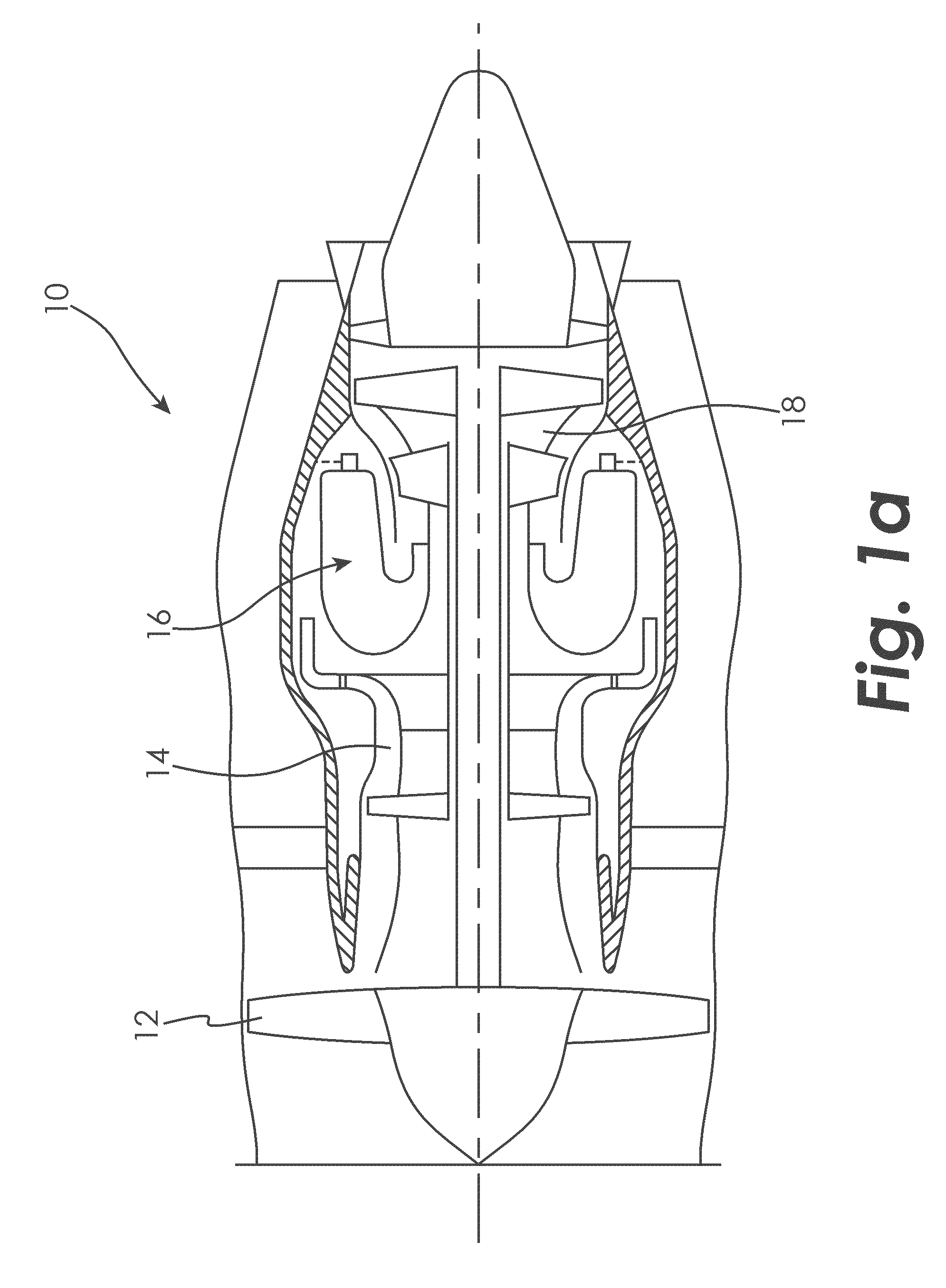
[0019]Although the embodiments disclosed herein may be used with any fuel system supplying any type of engine, a gas turbine engine and an auxiliary power unit are used as exemplary, non-limiting embodiments herein. FIG. 1A illustrates a gas turbine engine 10 of a type normally provided for use in a subsonic flight, generally comprising in serial flow communication a fan 12 through which ambient air is propelled, a compressor section 14 for pr...


PUM

PropertyMeasurementUnit
heataaaaaaaaaa
temperatureaaaaaaaaaa
meltingaaaaaaaaaa

Abstract

The presently disclosed embodiments utilize an ice separator vessel to trap ice particles in a non-homogeneous ice / fuel mixture flowing in a fuel system. A source of heat, such as heated fuel provided to the ice separator vessel, is used to melt at least a portion of the ice particles so that they do not enter the fuel system downstream of the ice separator vessel.

Description

CROSS REFERENCE TO RELATED APPLICATION[0001]This application claims the benefit of and incorporates by reference herein the disclosure of U.S. Ser. No. 61 / 767,388, filed Feb. 21, 2013.TECHNICAL FIELD OF THE DISCLOSURE[0002]The present disclosure generally related to fuel systems and, more specifically, to systems and methods for removing ice from a fuel system.BACKGROUND OF THE DISCLOSURE[0003]Fuel systems that supply fuel to engines are sometimes required to operate in extreme environments. For example, fuel systems supplying fuel to a gas turbine engine on an aircraft are expected to operate at high altitudes where ambient temperatures are very low. Consequently, the freezing of water and therefore the formation of ice in the liquid fuel is a concern. The performance of the engine will be adversely affected if ice entrained in the fuel reaches the engine.[0004]Therefore, systems and methods to remove ice that has formed in a fuel system are needed. The presently disclosed embodime...

Claims


Application Information

Patent Timeline
Patent Type & Authority Applications(United States)
IPC IPC(8): F02C7/224B01D21/00B01D21/26B04B15/02
CPCF02C7/224B01D21/262B04B15/02B01D21/009F02C7/236F05D2270/303F05D2260/606F05D2260/98F02M35/088
Inventor HAGSHENAS, BEHZAD
Owner RAYTHEON TECH CORP
Why Eureka
Try Eureka