Metrology-Based System for Operating a Flexible Manufacturing System

a flexible manufacturing and metal technology, applied in the field of aircraft fuselage construction, can solve the problems of inability to meet the requirements of inability to allow the construction of fuselages in the desired assembly facility or factory at desired assembly rate or desired assembly cost, and inability to accommodate different types and shapes of fuselages

Active Publication Date: 2016-01-14
THE BOEING CO
View PDF7 Cites 15 Cited by
  • Summary
  • Abstract
  • Description
  • Claims
  • Application Information

AI Technical Summary

Benefits of technology

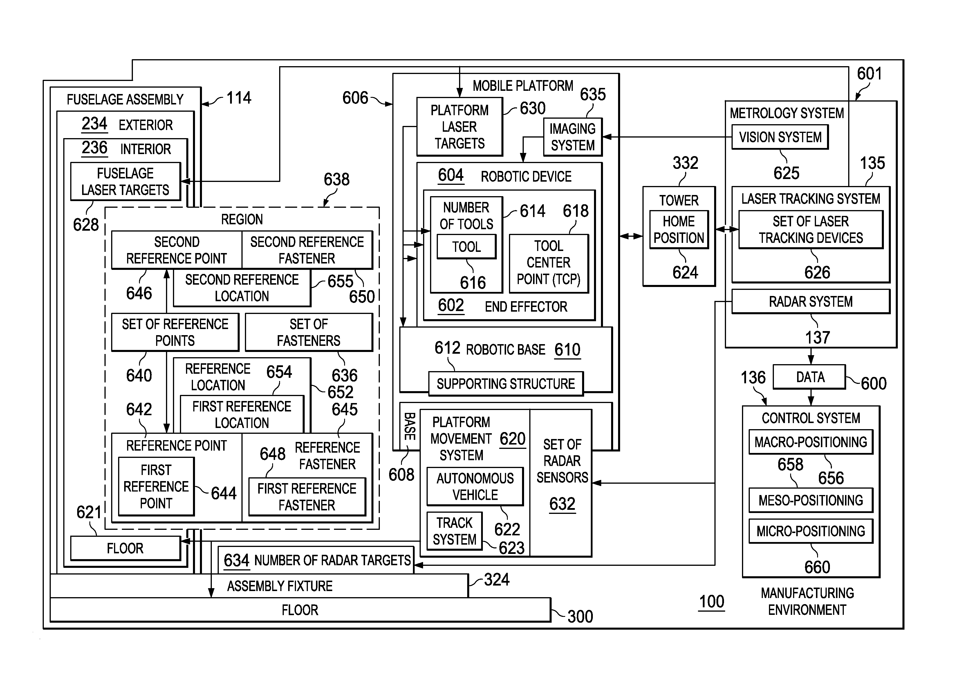
[0014]In still another illustrative embodiment, an apparatus may comprise a laser tracking system and a control system. The laser tracking system may comprise a set of laser tracking devices, fuselage laser targets associated with a fuselage assembly, and platform laser targets associated with a mobile platform. The control system may control positioning of an end effector relative to the fuselage assembly based on laser measurement data generated by the set of laser tracking devices.

Problems solved by technology

In some cases, this type of manual fastening process may be more labor-intensive, time-consuming, ergonomically challenging, or expensive than desired.
Further, some current assembly methods used to build fuselages that involve manual fastening processes may not allow fuselages to be built in the desired assembly facilities or factories at desired assembly rates or desired assembly costs.
These current assembly methods and systems may be unable to accommodate different types and shapes of fuselages.
Further, providing utilities, such as power, air, communications, hydraulic fluid, water, and other types of utilities, to the various systems used in some current assembly methods may be more difficult or cumbersome than desired.
For example, without limitation, the various cables and connection devices needed to provide these types of utilities to the different tools being used to assemble a fuselage may impede or restrict the movement of personnel and tools within a manufacturing environment.
These types of tracks may limit the flexibility and freedom of movement of these tools relative to the fuselage and require more human interaction than desired.
Further, these types of tracks may be unable to be used on certain areas of a fuselage.

Method used


Image

  • Metrology-Based System for Operating a Flexible Manufacturing System
  • Metrology-Based System for Operating a Flexible Manufacturing System
  • Metrology-Based System for Operating a Flexible Manufacturing System

Examples


Embodiment Construction

[0048]The illustrative embodiments recognize and take into account different considerations. For example, the illustrative embodiments recognize and take into account that it may be desirable to automate the process of building a fuselage assembly for an aircraft. Automating the process of building a fuselage assembly for an aircraft may improve build efficiency, improve build quality, and reduce costs associated with building the fuselage assembly. The illustrative embodiments also recognize and take into account that automating the process of building a fuselage assembly may improve the accuracy and precision with which assembly operations are performed, thereby ensuring improved compliance with outer mold line (OML) requirements and inner mold line (IML) requirements for the fuselage assembly.

[0049]Further, the illustrative embodiments recognize and take into account that automating the process used to build a fuselage assembly for an aircraft may significantly reduce the amount ...


PUM

PropertyMeasurementUnit
imagingaaaaaaaaaa
timeaaaaaaaaaa
shapesaaaaaaaaaa

Abstract

A method and apparatus for positioning an end effector relative to a fuselage assembly. A configuration of the fuselage assembly may be determined. The end effector may be positioned relative to the fuselage assembly based on the configuration determined. A set of actual reference locations may be identified for a set of reference points on the fuselage assembly. The end effector may be positioned at an operation location based on the set of actual reference locations identified.

Description

RELATED PROVISIONAL APPLICATION[0001]This application claims the benefit of U.S. Provisional Patent Application Ser. No. 62 / 022,641, filed Jul. 9, 2014, and entitled “Automated Flexible Manufacturing System for Building a Fuselage.”CROSS-REFERENCE TO RELATED APPLICATIONS[0002]This application is related to the following patent applications: entitled “Autonomous Flexible Manufacturing System for Building a Fuselage,” Ser. No. ______, attorney docket no. 14-0918-US-NP; entitled “Mobile Platforms for Performing Operations along an Exterior of a Fuselage Assembly,” Ser. No. ______, attorney docket no. 14-0901-US-NP; entitled “Mobile Platforms for Performing Operations inside a Fuselage Assembly,” Ser. No. ______, attorney docket no. 14-0902-US-NP; entitled “Wheel Mounting System,” Ser. No. ______, attorney docket no. 14-0903-US-NP; entitled “Dual-Interface Coupler,” Ser. No. ______, attorney docket no. 14-0904-US-NP; entitled “Clamping Feet for an End Effector,” Ser. No. ______, attorne...

Claims


Application Information

Patent Timeline
Patent Type & Authority Applications(United States)
IPC IPC(8): B25J11/00B25J9/16
CPCB25J9/1687B25J11/005Y10S901/02Y10S901/01B25J9/1697B64F5/10B64C1/00B64C1/12B64C1/068B64C2001/0072B64C1/069G05B19/41865G05B19/418G05B2219/45226B21J15/02B21J15/10B21J15/142B60G3/145B60G2204/143B60G2204/418B60G2206/8207B60G2300/60B25J5/007B25J11/007Y10S901/41B29C2793/0081Y02P90/80B64F5/50B23P2700/00B23P21/002B23P2700/01B29C65/70B21J15/28B25J9/1682F16B19/06B23P19/10B60G7/001B60G7/008B21J15/32B21J15/40G05B19/41805G05B2219/45071B25B5/163B29C39/123B29C39/22B29K2715/00B29L2031/748B64C1/06G05D1/0088G05D3/12B29C45/14336B29C39/026B29C39/10B29C2045/14368B60P3/025
Inventor OBEROI, HARINDER S.DORSEY-PALMATEER, JOHN WILLARDHU, YUANXIN CHARLESSARH, BRANKOBARRICK, KEVIN MARIONFINDLAY, MELISSA ANNARRIAGA, JORGE ALBERTOGUDZINSKI, GREGORY
Owner THE BOEING CO
Why Eureka
Try Eureka