Refrigeration cycle device

a technology of refrigerant cycle and device, which is applied in the direction of subcoolers, transportation and packaging, light and heating equipment, etc., can solve the problems of increasing the volume of the device storing the excessive amount of refrigerant in the cycle, and increasing the cost of refrigeran

Inactive Publication Date: 2016-01-14
DENSO CORP
View PDF2 Cites 15 Cited by
  • Summary
  • Abstract
  • Description
  • Claims
  • Application Information

AI Technical Summary

Benefits of technology

[0017]Thus, in the operation mode of allowing the refrigerant to flow through both the first and second evaporators, a pressure loss in the second return passage becomes large, so that the refrigerant pressure on the second evaporator side can be kept higher than that on the first evaporator side. If the refrigerant temperature of the seco

Problems solved by technology

The increase in the amount of sealed refrigerant leads to an increase in refrigerant cost.
The large difference in requi

Method used


Image

  • Refrigeration cycle device
  • Refrigeration cycle device
  • Refrigeration cycle device

Examples


first embodiment

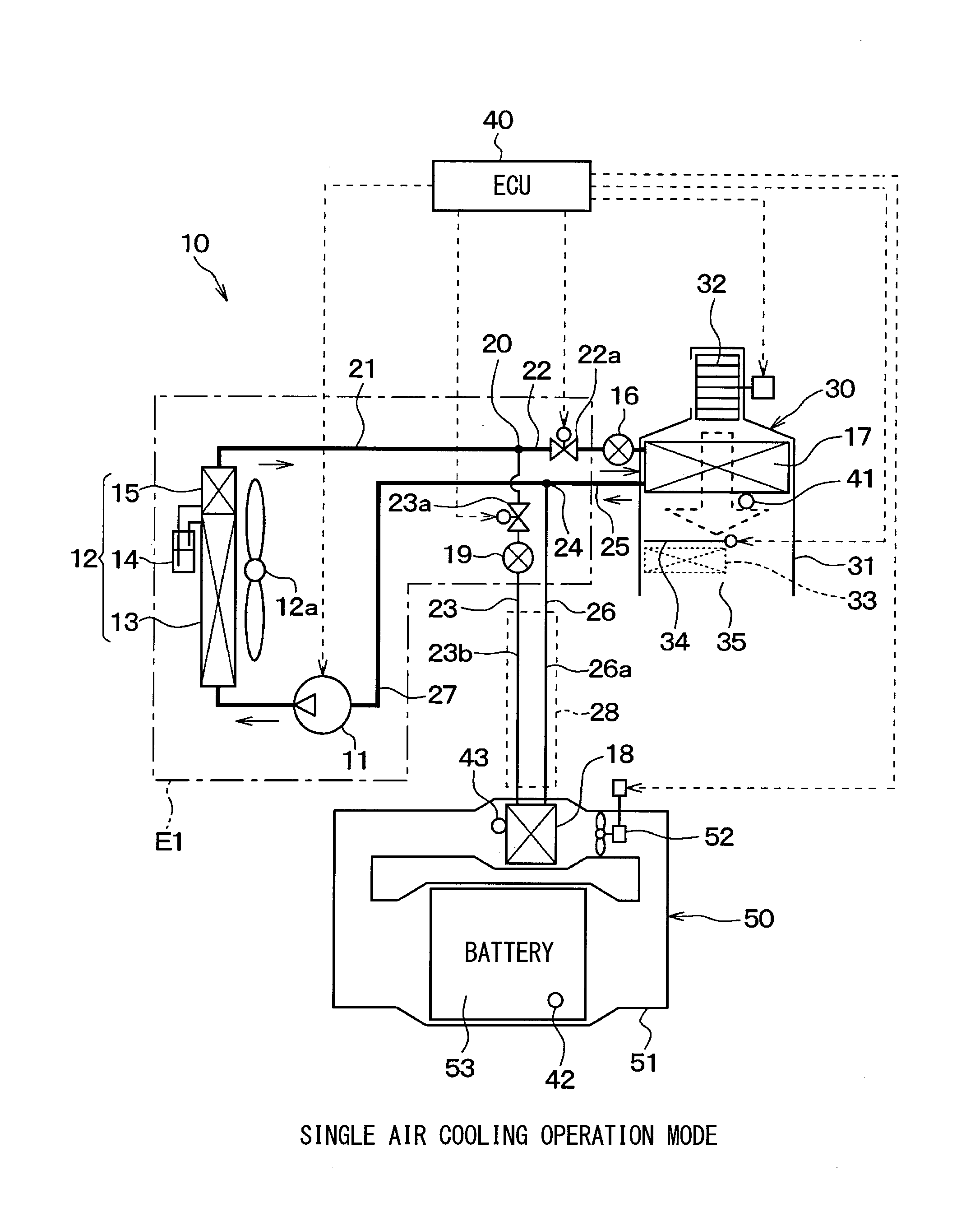
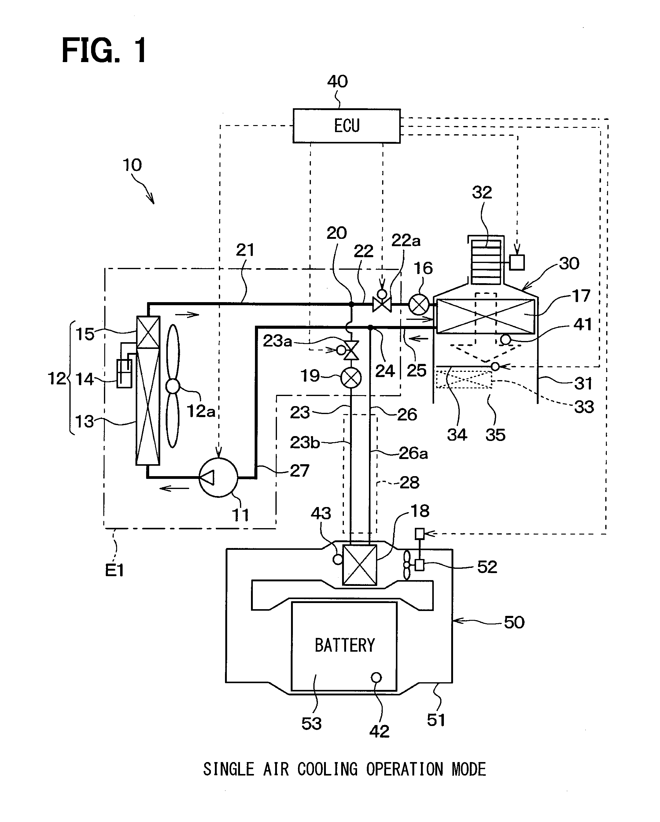
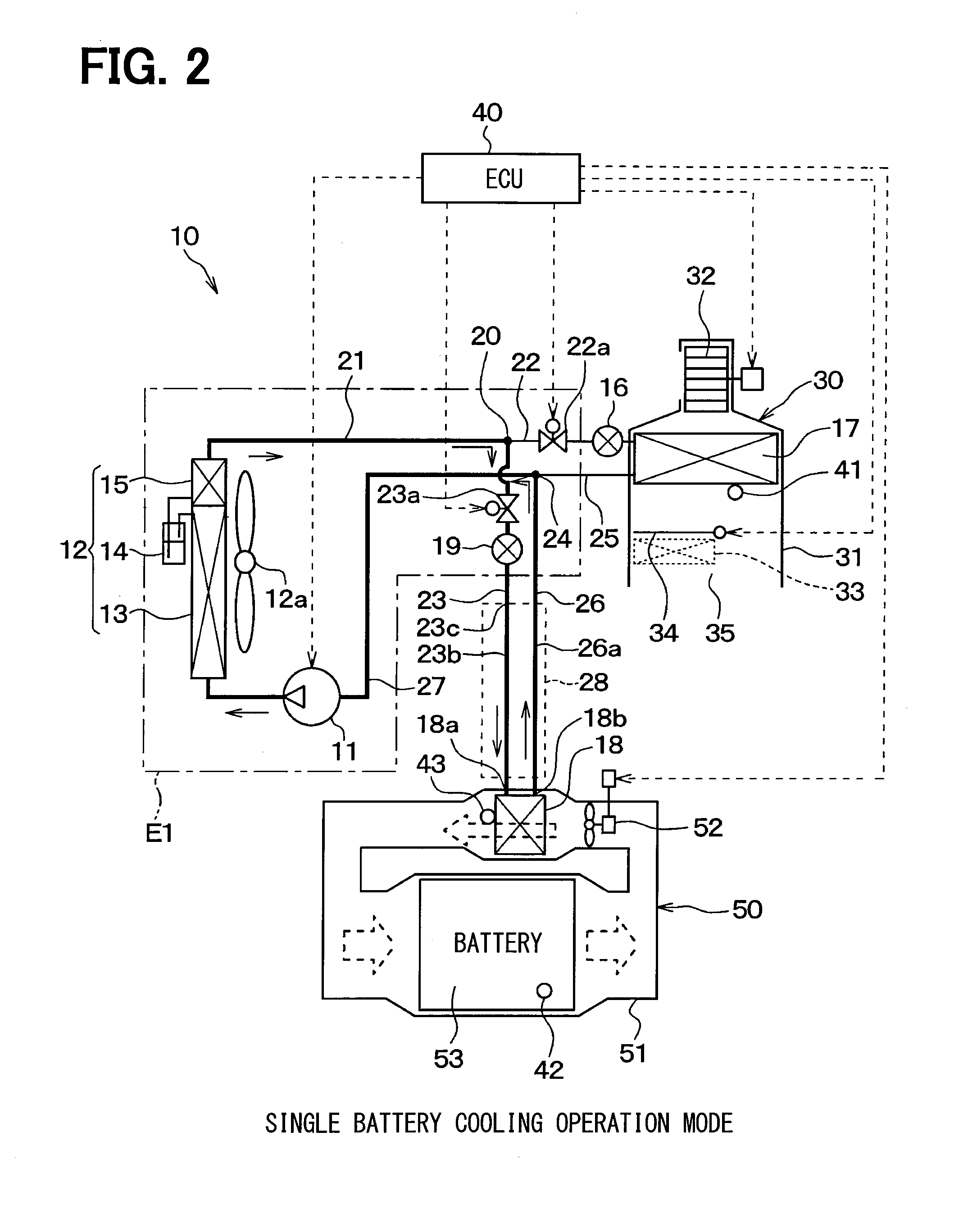
[0033]In a first embodiment, a refrigeration cycle device 10 according to the present disclosure is applied to a hybrid vehicle that can obtain a driving force for vehicle traveling from both an electric motor for traveling and an internal combustion engine. As shown in FIGS. 1 to 3, the hybrid vehicle uses the refrigeration cycle device 10 to cool the vehicle interior and also to cool a secondary battery 53 that stores therein electric power to be supplied to the electric motor for traveling.

[0034]The refrigeration cycle device 10 has a structure that includes a receiver cycle for air conditioning as a basic cycle, to which a secondary battery cooling function is added. The basic cycle has various devices, including a compressor 11, an exterior condenser 12, an air-cooling expansion valve 16, and an interior evaporator 17. These respective devices are connected together by refrigerant pipes. In the basic cycle, a battery-cooling evaporator 18 is disposed in parallel to the interior...

second embodiment

[0127]In the first embodiment, a receiver cycle that intends to perform air cooling is used as the basic cycle of the refrigeration cycle device 10. However, in a second embodiment as shown in FIG. 10, a heat pump cycle capable of performing both air cooling and heating is used. The structures of other components in the second embodiment are the same as those in the first embodiment.

[0128]The heat pump cycle is an accumulator cycle using an accumulator 61 instead of the gas-liquid separator 14 of the first embodiment. The heat pump cycle includes, in addition to the compressor 11, the exterior condenser 12, the air-cooling expansion valve 16, and the interior evaporator 17, an interior condenser 62, an air-heating expansion valve 63, a check valve 64 provided in the refrigerant flow path 21, and a bypass opening / closing valve 65a provided in a bypass flow path 65.

[0129]The accumulator 61 is a gas-liquid separator that separates the refrigerant, which is to be sucked into the compres...

third embodiment

[0135]Although in the second embodiment, the heat pump cycle capable of performing both the air cooling and heating operations is used as the basic cycle of the refrigeration cycle device 10, a third embodiment uses an accumulator cycle that performs only an air cooling operation as shown in FIG. 11.

[0136]The accumulator cycle omits the interior condenser 62, the air-heating expansion valve 63, the check valve 64, the bypass flow path 65, and the bypass opening / closing valve 65a from the accumulator cycle shown in FIG. 10. Also, the third embodiment can exhibit the same effects as those of the first embodiment.


PUM


Abstract

A first outward passage 22 and a second outward passage 23 are branched from a branch portion 20 to guide refrigerants to a first evaporator 17 and a second evaporator 18, respectively. In the second outward passage 23 with a longer refrigerant flow path of the first and second outward passages 22 and 23, a second decompressor 19 is disposed closer to the branch portion 20 rather than the second evaporator 18 in the second outward passage 23. Further, a part 23b of the second outward passage 23 located on the downstream side of the refrigerant flow with respect to the second decompressor 19 is defined by an inner pipe of a double pipe 28, and a part of a second return passage 26 is defined by an outer pipe of the double pipe 28.

Description

CROSS REFERENCE TO RELATED APPLICATION[0001]This application is based on a Japanese Patent Application 2012-281284 filed on Dec. 25, 2012, the contents of which are incorporated herein by reference in its entirety.FIELD OF THE INVENTION[0002]The present disclosure relates to a refrigeration cycle device that cools a plurality of objects to be cooled.BACKGROUND ART[0003]Conventionally, electric vehicles, including an electric automobile, and a hybrid vehicle, are designed to supply electric power stored in a secondary battery to an electric motor via an inverter or the like to thereby output a driving force for vehicle traveling. The secondary battery, typified by a lithium-ion battery, has its temperature increased by generation of Joule heat due to transfer of the electric power during traveling, charging, etc. If its temperature exceeds a predetermined temperature, the secondary battery might be degraded or broken. For this reason, a cooling device is required to maintain the batt...

Claims


Application Information

Patent Timeline
IPC IPC(8): F25B7/00
CPCF25B7/00B60H1/00278B60H1/00342B60H2001/00307F25B5/02F25B40/02F25B2400/0409F25B2400/0411F25B2400/23
Inventor TAKEUCHI, MASAYUKIYAMANAKA, TAKASHI
Owner DENSO CORP
Why Eureka
Try Eureka