
Liquid crystal display device

Active Publication Date: 2016-01-14
MATERIALS
View PDF15 Cites 16 Cited by
  • Summary
  • Abstract
  • Description
  • Claims
  • Application Information

AI Technical Summary

Benefits of technology

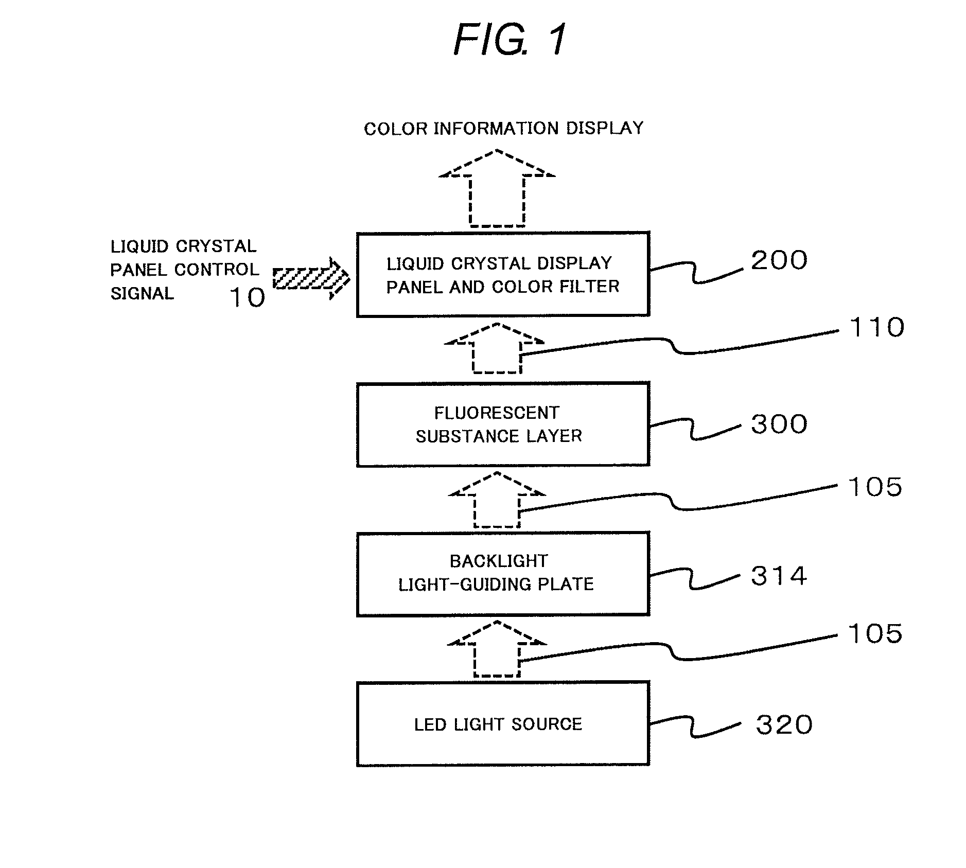
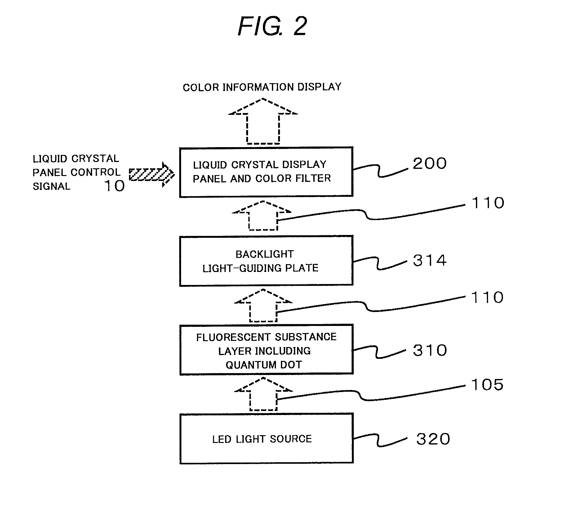
The described configuration in this patent allows for a thin and efficient liquid crystal display that uses less amounts of quantum dot fluorescent substance. The device is also flexible in terms of structure and color tone adjustment. The technical effects include higher efficiency, higher definition, and smaller thickness of the liquid crystal display device.

Problems solved by technology

A particle size of the fluorescent substance is as large as 10 or more times a wavelength of visible light (approximately 360 nm to 830 nm), and thus there is a problem in that scattering of light is likely to occur in a particle surface of the fluorescent substance, and an energy loss occurs.
In addition, only a surface of the fluorescent substance contributes a wavelength variation of light, and thus there is also a problem in that optical conversion for the volume of the fluorescent substance particles is not efficient.
In addition, with regard to the dope-type light-emitting particles, there is a problem in that a light-emitting wavelength, light-emitting intensity, and temperature dependency are approximately fixed in accordance with a kind of a dopant (light-emitting ion, atom).
Further, there is a problem in that a material capable of obtaining light-emitting intensity for practical use is limited.
Accordingly, a fluorescent substance capable of being used at one excitation wavelength is limited, and thus there is a problem in that the degree of freedom of a color tone is low.
As described above, the fluorescent substance of the related art has a lot of problems when being used as an optical material.
As a result, when using the fluorescent substance of the related art, the following problems are caused in a liquid crystal display device.
First, conversion efficiency into exciting light in a fluorescent substance, and extraction efficiency of the fluorescent substance are poor, and thus an energy loss increases.
In addition, spectral characteristics of a color filter in a liquid crystal display device, and a wavelength of fluorescence do not match each other, and thus an additional energy loss occurs.
Accordingly, power consumption of the liquid crystal display device increases more than necessary.
Specifically, it is necessary to use a lot of quantum dot fluorescent substances, it is necessary to apply a fluorescent substance to a wide area in a uniform concentration, and it is difficult to make the physical thickness of the liquid crystal display device small.
However, in the method of Patent Literature 5, it is difficult to use a light source with a small size and high efficiency, and thus a cold-cathode tube is used.
Accordingly, it is possible to make the periphery of the liquid crystal display device in a planar direction narrow, but the backlight becomes expensive.
Therefore, it is necessary to emit strong light so as to compensate the optical loss due to the fluorescent substance layer, and thus there are problems in that an operational lifespan shortens due to an increase in heat generation in the light-emitting diode, an operational lifespan of the fluorescent substance layer shortens due to exposition of the fluorescent substance to the strong LED light, and the like.
Accordingly, it is difficult to provide the fluorescent substance layer in a region with a narrow area which is close to the LED.
In the dope-type light-emitting element, a light-emitting wavelength and the like are fixed in accordance with the kind of a dopant, and thus it is difficult to allow the excitation wavelength and the light-emitting wavelength to match each other, and as a result, light-emitting efficiency is low.
Particularly, this problem becomes significant in the vicinity of red light.

Method used


Image

  • Liquid crystal display device
  • Liquid crystal display device
  • Liquid crystal display device

Examples


second embodiment

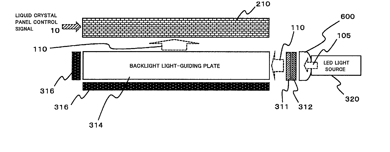
[0064]FIG. 7 illustrates light source arrangement in the liquid crystal display device in FIGS. 5(a) and 5(b) according to the invention in detail. Light (105), which is emitted from the LED light source (320), is transmitted through the convex lens column (600) and is incident to the fluorescent substance layers (311, 312), which include a quantum dot, on a front surface side of the convex lens column (600). In the fluorescent substance layers (311, 312), wavelength conversion is carried out with respect to the light, which is incident, through light emission of a fluorescent substance, and the incident light and the light that is converted with the fluorescent substance layers (311, 312) are synthesized to form white light (110). The white light (110), which is synthesized, enters the backlight light-guiding plate (314). The white light (110) is scattered in the backlight light-guiding plate (314), is diffused to the entirety of the light-guiding plate, and is output from the back...

third embodiment

[0067]FIG. 8 is a diagram illustrating the invention. As illustrated in FIG. 8, the liquid crystal display device is provided with a convex lens column (600), in which fine quantum dot fluorescent substance particles of 50 nm or less are diffused in a transparent material, and has a wavelength conversion function with a fluorescent substance, as a fluorescent substance layer. In a case of using a blue LED, two kinds of wavelength conversion of red R and green G are necessary, and thus two kinds of quantum dot fluorescent substances such as a quantum dot fluorescent substance (quantum dot having a particle size of 50 nm or less (fluorescent substance particles) (red)) (800), and a quantum dot fluorescent substance (quantum dot having a particle size of 50 nm or less (fluorescent substance particles) (green)) (801) are included in the convex lens column (600).

[0068]In this configuration, the quantum dot fluorescent substance particles are diffused in the convex lens column (600) to fo...


PUM


Abstract

There is provided a high-efficiency and high-definition liquid crystal display device in which a white light source is constituted by using a fluorescent substance composed of a quantum dot having a minute particle size, and an LED light-emitting element, light from the light source is allowed to be incident from one lateral surface of a backlight provided on a rear surface of the liquid crystal display device, and thus an amount of the quantum dot fluorescent substance that is used is reduced, and the thickness of the liquid crystal display device is made smaller as a whole.

Description

TECHNICAL FIELD[0001]The present invention relates to a high-efficiency and high-definition liquid crystal display device in which a backlight is constructed by using a fluorescent substance composed of a quantum dot, and an LED light-emitting element, and which has an inexpensive structure.BACKGROUND ART[0002]The liquid crystal display device is a display device using a liquid composition. The liquid crystal display device is widely used as a display device in various apparatuses, particularly, as an information display device and an image display device. The liquid crystal display device displays an image by transmitting or blocking light for each region on the basis of application of a voltage. Accordingly, external light is necessary for display of an image on the liquid crystal display device. Accordingly, a backlight, which is provided on a rear surface of the liquid crystal display device, is used as a light source. The backlight is used to irradiate the entirety of the liqui...

Claims


Application Information

Patent Timeline
IPC IPC(8): F21V8/00G02F1/1335
CPCG02B6/003G02F2001/133614G02F1/1336G02B6/0073G02F2202/36G02B6/0023G02F1/133603G02F1/133615G02F2202/108G02F1/133614
Inventor KOKUDO, SHINGOKANAUMI, EIICHI
Owner MATERIALS
Learn More