Optical lens, method for producing same, lens unit, image-capturing module, and electronic device

a technology of optical lens and lens unit, which is applied in the field of optical lens, can solve the problems that the effect of external light or internal reflected light in the lens cannot be perfectly eliminated, the effect of unnecessary light cannot be reliably eliminated, and the effect of preventing the phenomenon of flashes and ghosts cannot be perfectly prevented

Inactive Publication Date: 2016-01-14
FUJIFILM CORP
View PDF7 Cites 39 Cited by
  • Summary
  • Abstract
  • Description
  • Claims
  • Application Information

AI Technical Summary

Benefits of technology

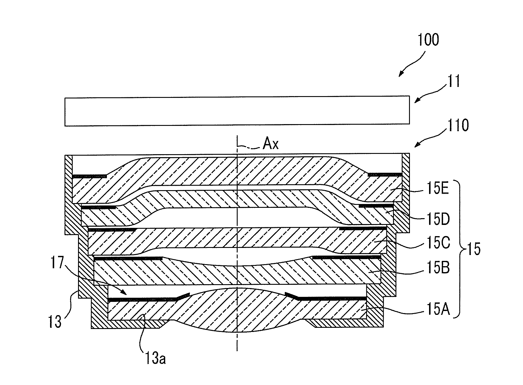
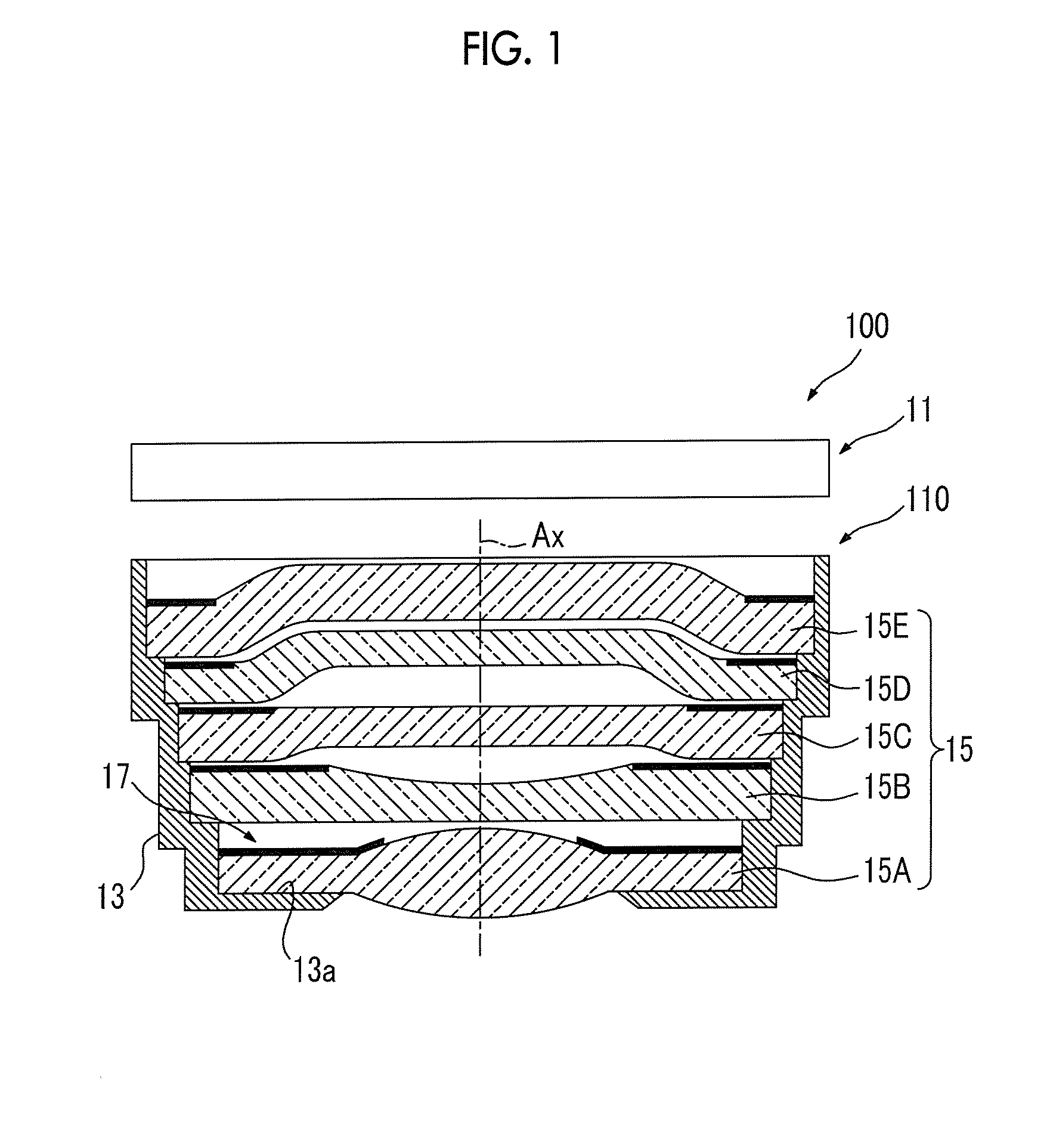
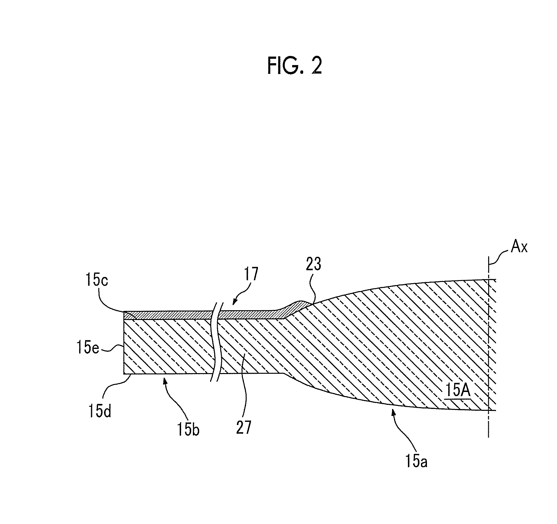
[0009]The present invention has been made in view of the above-mentioned situation to provide an optical lens, a method for producing the same, a lens unit, an imaging module, and an electronic device capable of preventing stray light from occurring by restricting surface reflection on the light shielding film.
[0016]According to the present invention, stray light is prevented from occurring by restricting surface reflection on the light shielding film of the optical lens, and unnecessary light is reliably eliminated.

Problems solved by technology

However, even if the light shielding sheet is provided around the lens section, stray light occurs, and thus flares and ghosts cannot be perfectly prevented from occurring.
Further, even when the light shielding film is directly formed on the lens surface, stray light occurs.
As described above, even when the light shielding sheet is disposed, or even when the light shielding film is formed on the lens surface, in practice, the effect caused by outside light or internal reflected light in the lens cannot be perfectly eliminated.

Method used


Image

  • Optical lens, method for producing same, lens unit, image-capturing module, and electronic device
  • Optical lens, method for producing same, lens unit, image-capturing module, and electronic device
  • Optical lens, method for producing same, lens unit, image-capturing module, and electronic device

Examples


example 1

[0066]An ultraviolet curable ink having the following composition was applied onto the substrate in the ink jet method, thereby forming the light shielding film.

[0067]

[0068]Monomer: 85%, polymerization initiator: 10%, additives: 3%, diphenyl-2,4,6-trimethylbenzoylphosphine oxide: 1%, carbon black: 1%

[0069]The laser blasting process was performed on the light shielding film with laser conditions shown in the following Table 1, thereby roughening the light shielding film surface.

TABLE 1Wavelength1060nmPulse period100kHzPulse width20nsDiameter of laser spot0.05mmφBeam scanning speed2000mm / sEnergy26J / mm2Peak power2kW

[0070]Regarding the light shielding film which is not roughened, assuming that an incident angle of light vertically incident onto the surface is 0°, a gloss level of the light shielding film, which is obtained when light is incident at an incident angle of 60°, was measured. Further, regarding the roughened light shielding film, likewise, the gloss level of the light shield...

example 2

[0071]An antireflective coat was formed on a surface of a lens made of ZEONEX (registered trademark) grade F52R manufactured by Zeon Corporation. The antireflective coat had a 4-layer structure (thickness of 0.2 μm) in which SiO2 and ZrO2 were alternately superimposed, and was formed such that the surface exposed to air was SiO2. This lens surface was irradiated with laser light under the same conditions as those in Example 1, so that the surface was roughened, and transmittances of the lens before and after roughening were measured. Three lenses were provided, and the measurement was performed on the lenses. Measurement results are shown in Table 2. In Table 2, “ave” indicates an average of three measured values.

TABLE 2n = 1n = 2n = 3aveBefore laser92.97%93.05%93.05%93.02%processAfter laser93.19%93.31%93.30%93.27%process

[0072]As shown in Table 2, it was discovered that the difference in transmittance between before and after the laser process was 0.25%, which was within a measureme...


PUM


Abstract

An optical lens includes a lens section that transmits light therethrough; and a light shielding section provided close to the lens section, the light shielding section having a light shielding film formed on a surface of a lens base material. The surface layer of at least a part of the light shielding film including an inner edge thereof on a lens section side, and a boundary portion of the lens section in contact with the light shielding layer is subjected to a roughening process.

Description

CROSS-REFERENCE TO RELATED APPLICATIONS[0001]This application is a Continuation of PCT International Application No. PCT / JP2014 / 057650 filed on Mar. 20, 2014, which claims priority under 35 U.S.C §119(a) to Japanese Patent Application No. 2013-064110 filed on Mar. 26, 2013 and Japanese Patent Application No. 2014-040559 filed on Mar. 3, 2014. Each of the above applications is hereby expressly incorporated by reference, in its entirety, into the present application.BACKGROUND OF THE INVENTION[0002]1. Field of the Invention[0003]The present invention relates to an optical lens, a method for producing the same, a lens unit, an imaging module, and an electronic device.[0004]2. Description of the Related Art[0005]Imaging modules, which are built into and used in electronic devices such as digital cameras and mobile phones, have improved in image quality of a photographic image by removing unnecessary incident light so as to prevent flares and ghosts from occurring. As measures for image ...

Claims


Application Information

Patent Timeline
Patent Type & Authority Applications(United States)
IPC IPC(8): G02B27/00G02B1/111G02B1/12G02B13/00H04N5/225
CPCG02B27/0018G02B13/001G02B1/12G02B1/111H04N5/225G02B13/0045G02B5/003G02B5/005H04N23/00
Inventor TAKADA, GOROH
Owner FUJIFILM CORP
Why Eureka
Try Eureka