
Image forming apparatus

a technology of image processing and forming apparatus, which is applied in the direction of digital output to print units, visual presentation using printers, instruments, etc., can solve the problems of data transfer from image processing units, bottleneck of productivity, and complex processes

Active Publication Date: 2016-01-14
RICOH KK
View PDF2 Cites 17 Cited by
  • Summary
  • Abstract
  • Description
  • Claims
  • Application Information

AI Technical Summary

Benefits of technology

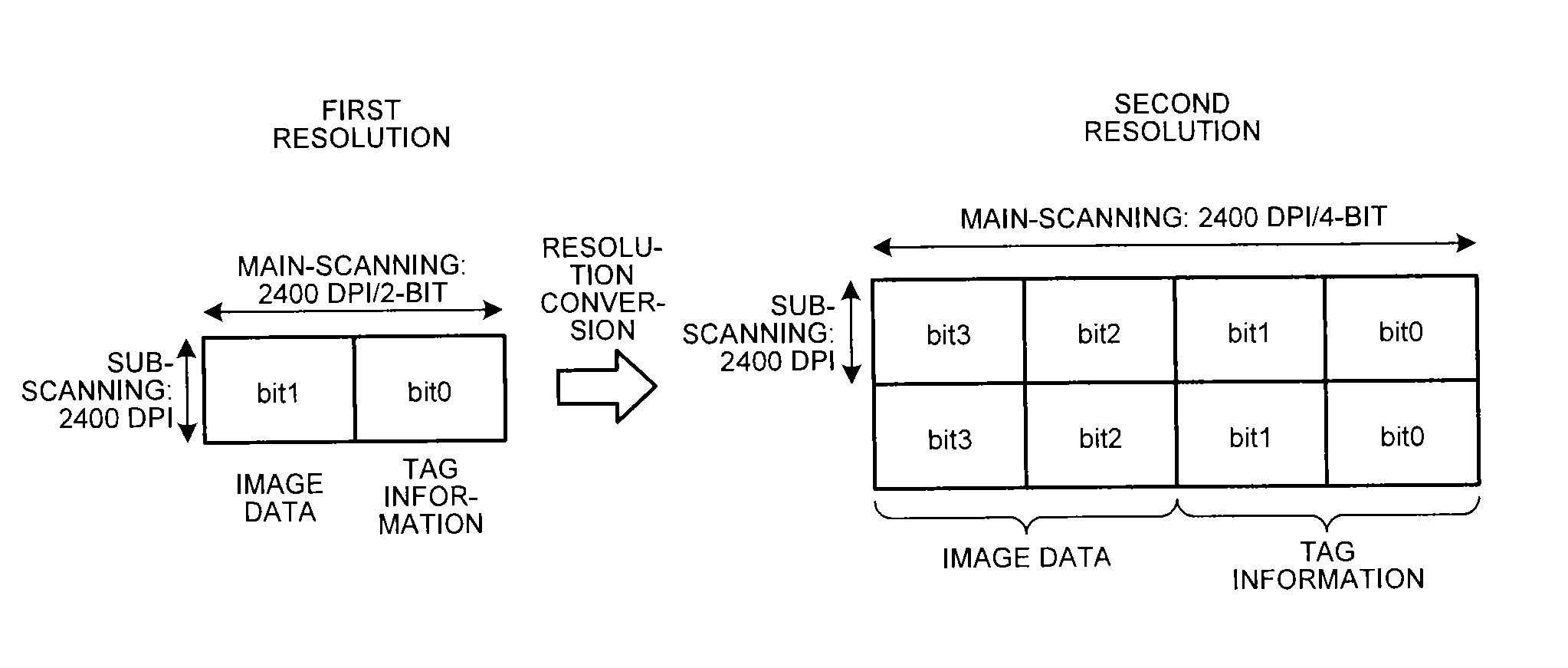
The present invention provides an image forming apparatus that can create high-quality images. It includes an image processing unit that creates image data with a low resolution and tag information indicating whether or not each pixel is a pixel of a character or a line. A conversion unit then sequentially selects target pixels and converts the image data to higher resolution image data for each target pixel using a pattern matching process. This results in images that have more detail and better quality. The light source is driven by a modulation signal corresponding to the higher resolution image data.

Problems solved by technology

Incidentally, if image processing is performed with a high density, a defect may occur in data transfer from the image processing unit to a light source driving circuit on the downstream side.
However, if the image processing is performed with a high density, the amount of data transferred from the image processing unit to the light source driving circuit on the downstream side greatly increases, which is the bottleneck of the productivity.
If all of the processes for improving the reproducibility of minute characters or the like are performed by the image processing unit on the upstream side, the processes become complex and loads on the image processing unit increase.

Method used


Image

  • Image forming apparatus
  • Image forming apparatus
  • Image forming apparatus

Examples


Embodiment Construction

[0050]A color printer 2000, which is an example of an image forming apparatus as an embodiment of the present invention, will be described in detail below with reference to the accompanying drawings.

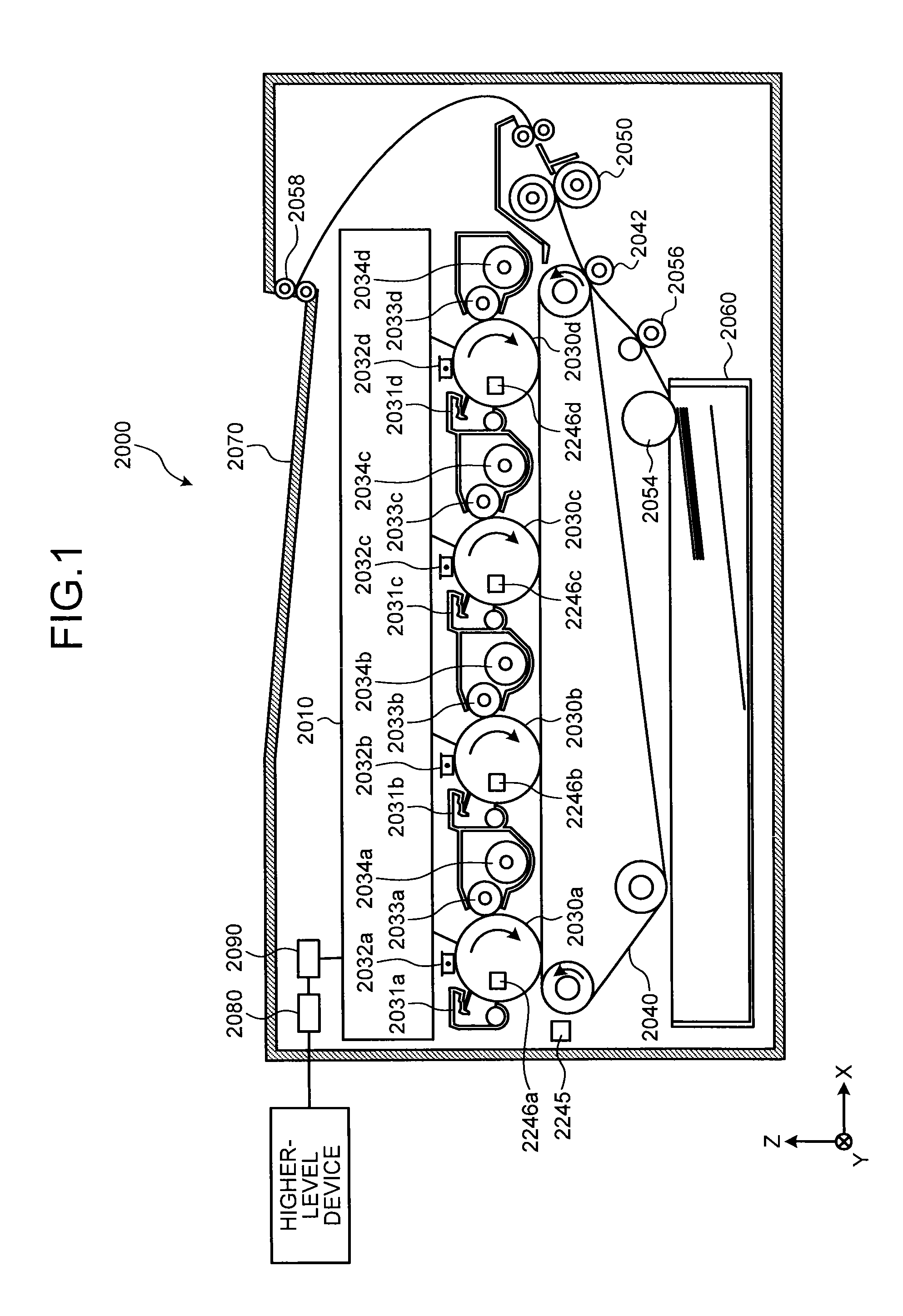
[0051]FIG. 1 is a diagram illustrating a schematic configuration of the color printer 2000 according to the embodiment. The color printer 2000 generates a printed material by transferring toner to a recording paper (object). The color printer 2000 is a multicolor printer of a tandem system that forms a full-color image by superimposing four colors (black, cyan, magenta, and yellow).

[0052]The color printer 2000 includes an optical scanning device 2010, four photoconductor drums 2030a, 2030b, 2030c, and 2030d (all four may be collectively referred to as photoconductor drums 2030), four cleaning units 2031a, 2031b, 2031c, and 2031d (all four may be collectively referred to as cleaning units 2031), and four charging devices 2032a, 2032b, 2032c, and 2032d (all four may be collectively referre...


PUM


Abstract

An apparatus includes an image-processing-unit that generates tag information indicating whether each of pixels of a first-resolution image data is a pixel of a character or a line, a resolution-converting-unit that converts the first-resolution image data to image data with a second resolution higher than the first resolution, and a light-source-driving-unit that drives light-source according to the second-resolution image data. The resolution-converting-unit includes an image-matrix-acquiring-unit that acquires an image matrix being image data and tag information with the first resolution in an area containing a target-pixel and pixels around the target-pixel, a pattern-matching-unit that determines whether the target-pixel is a pixel of an edge of a character or a line based on the image matrix, and a first-converting-unit that, when the pixel is the edge pixel, converts the image data to image data with the second resolution of a pattern determined in accordance with a layout of the target-pixel.

Description

CROSS-REFERENCE TO RELATED APPLICATIONS[0001]The present application claims priority to and incorporates by reference the entire contents of Japanese Patent Application No. 2014-144514 filed in Japan on Jul. 14, 2014.BACKGROUND OF THE INVENTION[0002]1. Field of the Invention[0003]The present invention relates to an image forming apparatus.[0004]2. Description of the Related Art[0005]In recent years, digital printers employing an electrophotographic process have been increasingly used in the field of production printing. Therefore, there is a demand to improve image quality and reliability in the digital printers employing the electrophotographic process. In particular, in the digital printers employing the electrophotographic process, there is a demand to improve the reproducibility of thin lines, improve the reproducibility of characters (improve the reproducibility of characters with minute sizes corresponding to two or three points, for example), prevent thickening of the charact...

Claims


Application Information

Patent Timeline
IPC IPC(8): G06K15/02G06F3/12G06K15/00G06K15/14
CPCG06K15/1874G06K15/14G06K15/4055G06F3/122G06F3/1208G06K15/1822H04N1/40062H04N1/40068
Inventor IWATA, MUNEAKIISHIDA, MASAAKIOMORI, ATSUFUMIWATANABE, NAOTOFUJITA, HAYATO
Owner RICOH KK
Learn More