Gate driving unit, gate driving circuit, and display device

a gate driving circuit and display device technology, applied in the field of display technology, can solve the problems of affecting the small size of the display panel, the complexity of the circuit connection, and the large area of the whole gate driving circuit, so as to reduce the number of gate driving units and reduce the charge time. , the effect of high efficiency

Active Publication Date: 2016-01-14
BOE TECH GRP CO LTD +1
View PDF21 Cites 33 Cited by
  • Summary
  • Abstract
  • Description
  • Claims
  • Application Information

AI Technical Summary

Benefits of technology

[0026]The advantageous technical effects of the present invention are as follows. As compared with a gate driving unit which can output only a gate driving signal of one row of pixel units in the prior art, the gate driving unit provided by the present invention has a higher efficiency by inputting gate driving signals of two rows of pixel units to the input terminals of the input circuit and the input terminals of the reset circuit, and outputting gate driving signals of two rows of pixel units from the output terminals of the output circuit. In the gate driving circuit provided by the present invention, an area occupied by the whole gate driving circuit is reduced due to that the number of the gate driving units is reduced. In addition, since gate driving signals of two adjacent rows of pixel units which are out put by two adjacent gate driving units have an interval of ¼ cycle, a charge time is reduced and a charge efficiency is increased. Thus, a driving efficiency of the whole gate driving circuit is increased.

Problems solved by technology

Since the above gate driving circuit is composed of n gate driving units, the circuit connection thereof is complicated and an area of the whole gate driving circuit is large.
Thus, an area occupied by the gate driving circuit on a substrate is also large, which hinders a display panel to have a small size and a low cost.

Method used


Image

  • Gate driving unit, gate driving circuit, and display device
  • Gate driving unit, gate driving circuit, and display device
  • Gate driving unit, gate driving circuit, and display device

Examples


embodiment 1

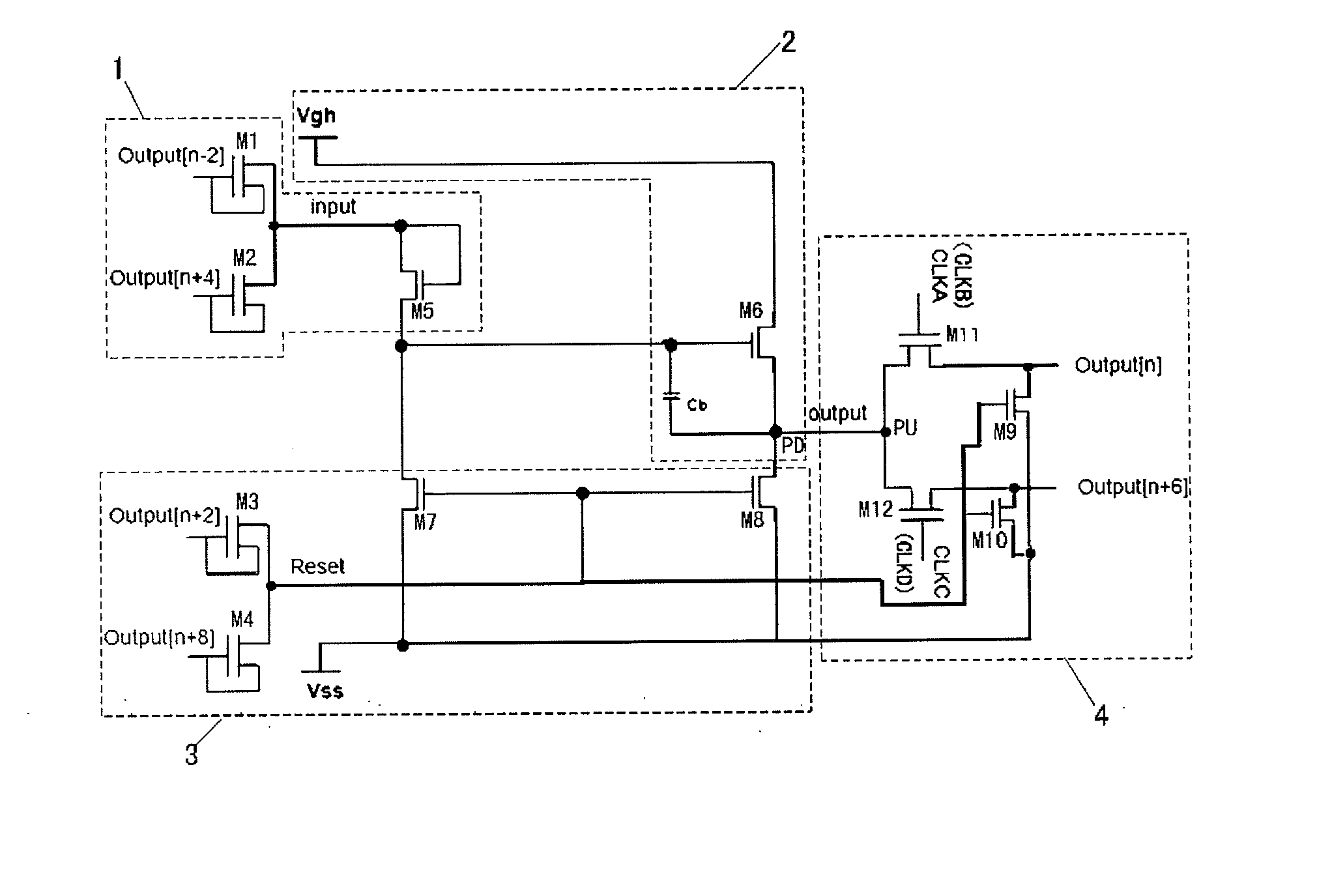
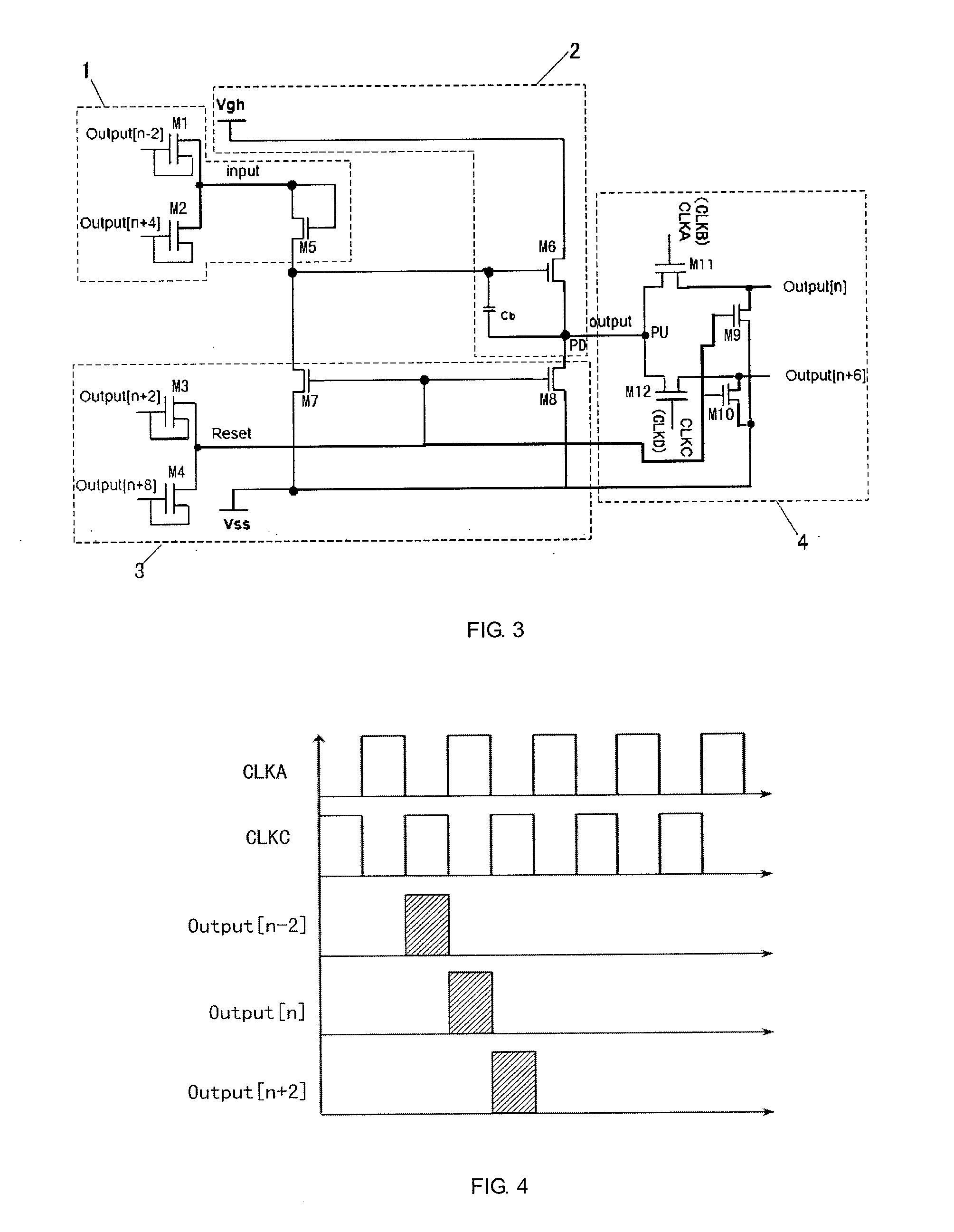
[0038]The present embodiment provides a gate driving unit, as shown in FIG. 3. The gate driving unit includes an input circuit 1, a pull-up circuit 2, a reset circuit 3, and an output circuit 4. The input circuit 1 is connected to both the pull-up circuit 2 and the reset circuit 3, and the pull-up circuit 2 and the reset circuit 3 are connected to the output circuit 4, respectively. Wherein,

[0039]the input circuit 1 is used for receiving a pull-up driving signal and inputting the pull-up driving signal to the pull-up circuit 2;

[0040]the pull-up circuit 2 is used for receiving the pull-up driving signal and outputting a high level signal to an input terminal PU of the output circuit 4;

[0041]the reset circuit 3 is used for receiving a reset driving signal and resetting the high level signal at the input terminal PU of the output circuit 4 to a low level signal; and

[0042]the output circuit 4 is used for receiving an output signal from the pull-up circuit 2 and an output signal from the...

embodiment 2

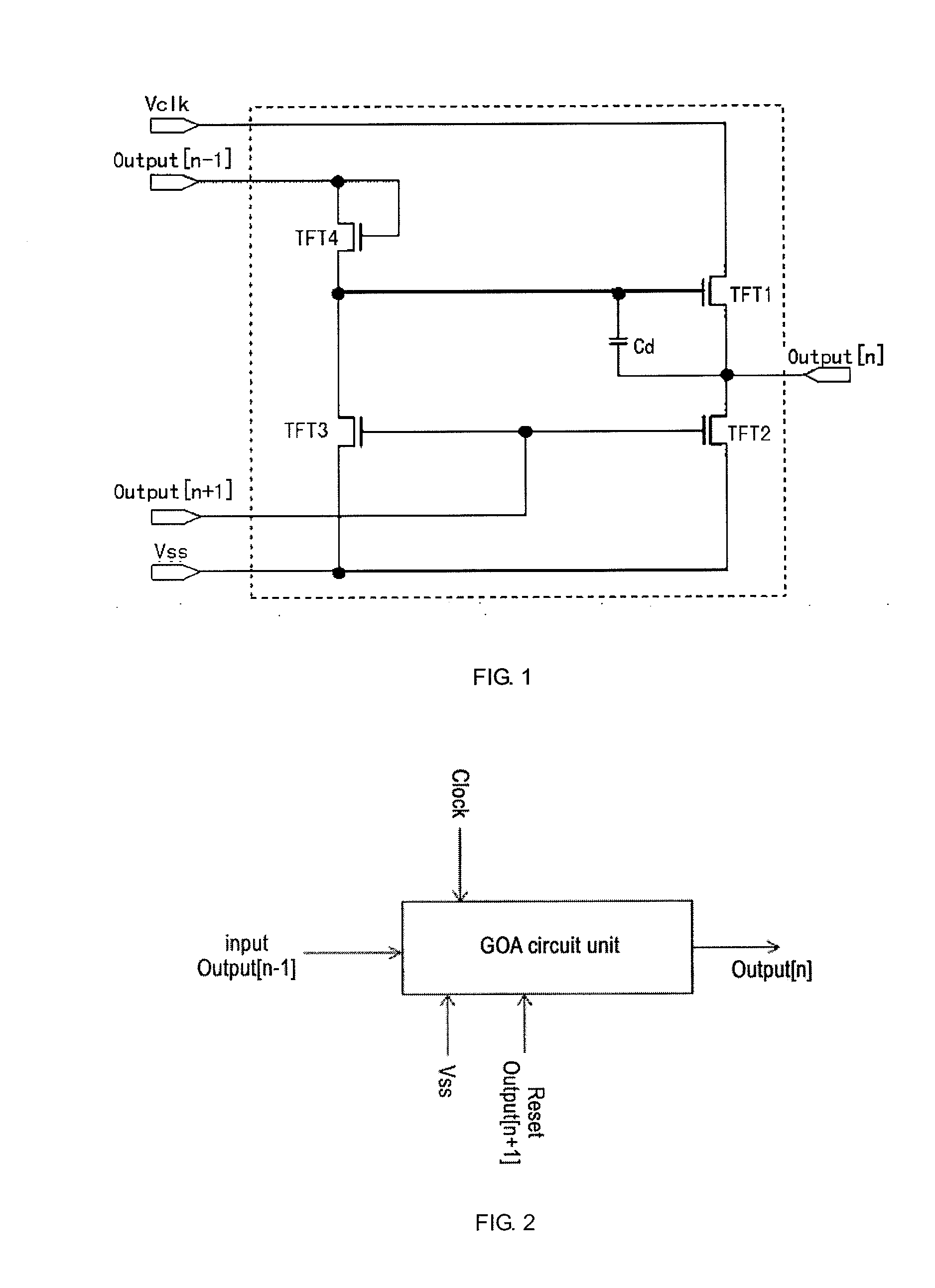
[0064]The present embodiment provides a gate driving circuit including the above gate driving units GOA, as shown in FIG. 5. The gate driving circuit includes a plurality of the gate driving units GOA which are cascaded sequentially. The plurality of the gate driving units GOA alternately use the first clock signal CLKA and the third clock signal CLKC, and the second clock signal CLKB and the fourth clock signal CLKD sequentially and cyclically. That is, one of the two adjacent gate driving units uses the first clock signal CLKA and the third clock signal CLKC, the other of the two adjacent gate driving units uses the second clock signal CLKB and the fourth clock signal CLKD.

[0065]In the present embodiment, every two adjacent ones of the four clock signals used by the two adjacent gate driving units GOA have an interval of ¼ cycle therebetween. That is, the first clock signal CLKA and the second clock signal CLKB have an interval of ¼ cycle therebetween, the second clock signal CLKB...

embodiment 3

[0081]The present embodiment provides a display device including the gate driving circuit according to Embodiment 2.

[0082]Since the above gate driving circuit is used, on one hand, an area occupied by the gate driving circuit on a display panel in the display device is reduced, and on the other hand, the refresh efficiency when the display device performs display is increased.


PUM


Abstract

A gate driving unit includes an input circuit, a pull-up circuit, a reset circuit, and an output circuit. The pull-up driving signals received by the input circuit include the gate driving signals for pixel units of row n−2 and row n+4. The reset driving signals received by the reset circuit include the gate driving signals for pixel units of row n+2 and row n+8. The gate driving signals output from the output circuit include the gate driving signals for pixel units of row n and row n+6. Where, n is a positive integer and nε[3,∞). The gate driving unit can output gate driving signals of two rows of pixel units and thus has a high service efficiency. An area occupied by a gate driving circuit made of the gate driving units is reduced, and a driving efficiency of the gate driving circuit is increased.

Description

FIELD OF THE INVENTION[0001]The present invention relates to the field of display technology, and in particular, relates to a gate driving unit, a gate driving circuit, and a display device.BACKGROUND OF THE INVENTION[0002]Nowadays, a liquid crystal display (LCD) and an organic light-emitting diode (OLED) display device are still mainstream products of flat panel display. In a liquid crystal display and an active matrix OLED display device, thin film transistors (TFTs) are generally used for controlling respective pixel units to achieve image display. Control of pixel units includes control of rows and control of columns. The control of rows is generally achieved by using a gate driving circuit for scanning pixel units row by row, and the gate driving circuit (e.g., a Gate driver On Array (GOA)) has been well developed till now. The control of columns is generally achieved by using a data driving circuit for scanning pixel units column by column, thereby transmitting display data.[0...

Claims


Application Information

Patent Timeline
Patent Type & Authority Applications(United States)
IPC IPC(8): G09G3/20
CPCG09G3/2092G09G2310/0218G09G2310/0248G09G2310/08G09G2310/021G09G3/3266G09G3/3677G09G2310/0267G09G2310/0286G11C19/28
Inventor XU, XIANGYANG
Owner BOE TECH GRP CO LTD
Why Eureka
Try Eureka