Multi-cell transducer

a multi-cell, transducer technology, applied in piezoelectric/electrostrictive transducers, mechanical vibration separation, generators/motors, etc., can solve the problems of reducing the acoustic output power of the interaction between the elements of the array, and affecting the acoustic output power of the array. achieve the effect of wide acoustic field, low profile and high sensitivity

Active Publication Date: 2016-01-14
MICROTECH MEDICAL TECH
View PDF7 Cites 16 Cited by
  • Summary
  • Abstract
  • Description
  • Claims
  • Application Information

AI Technical Summary

Benefits of technology

[0017]It is another object of the invention to provide a method for fabricating an electroacoustic transducer having a low profile, high sensitivity and a wide acoustic field.
[0018]It is yet another object of the invention to provide a method for fabricating an electroacoustic transducer having a low profile, high sensitivity and a narrow acoustic field.
[0019]The collective effect of the planar array of cells in accordance with the invention gives the transducer device the advantage of higher sensitivity operating over a larger bandwidth compared to single cell transducers. The construction of the transducer also provides a low profile and lightweight device with a flexible design that is relatively inexpensive to prototype. The transducer of the invention may be designed to provide an appropriate field strength, field width and frequency or combination of frequencies for a variety of applications.

Problems solved by technology

Nevertheless, interactions between individual elements of closely packed arrays can lead to different acoustic loading on each transducer element, depending on its location in the array, which can lead to variations in the volume velocity of each element in the array.
This can cause significant variations in the volume intensity of each array element.
Thus, despite the improvements to power and signal to noise ratios that a transducer array can provide, the interactions between elements of the array can actually reduce acoustic output power; in extreme cases, individual elements of the array may have negative radiation resistance and actually absorb acoustic power.
Such interactions can be especially problematic when transducer elements are small compared to the wavelength of the radiated field and when they have a high efficiency.
Commercially available ultrasonic emitting devices having electroacoustic transducers are generally large and bulky with insufficient transmission sensitivity and bandwidth for optimal use with implanted sensors.

Method used


Image

  • Multi-cell transducer
  • Multi-cell transducer
  • Multi-cell transducer

Examples


Embodiment Construction

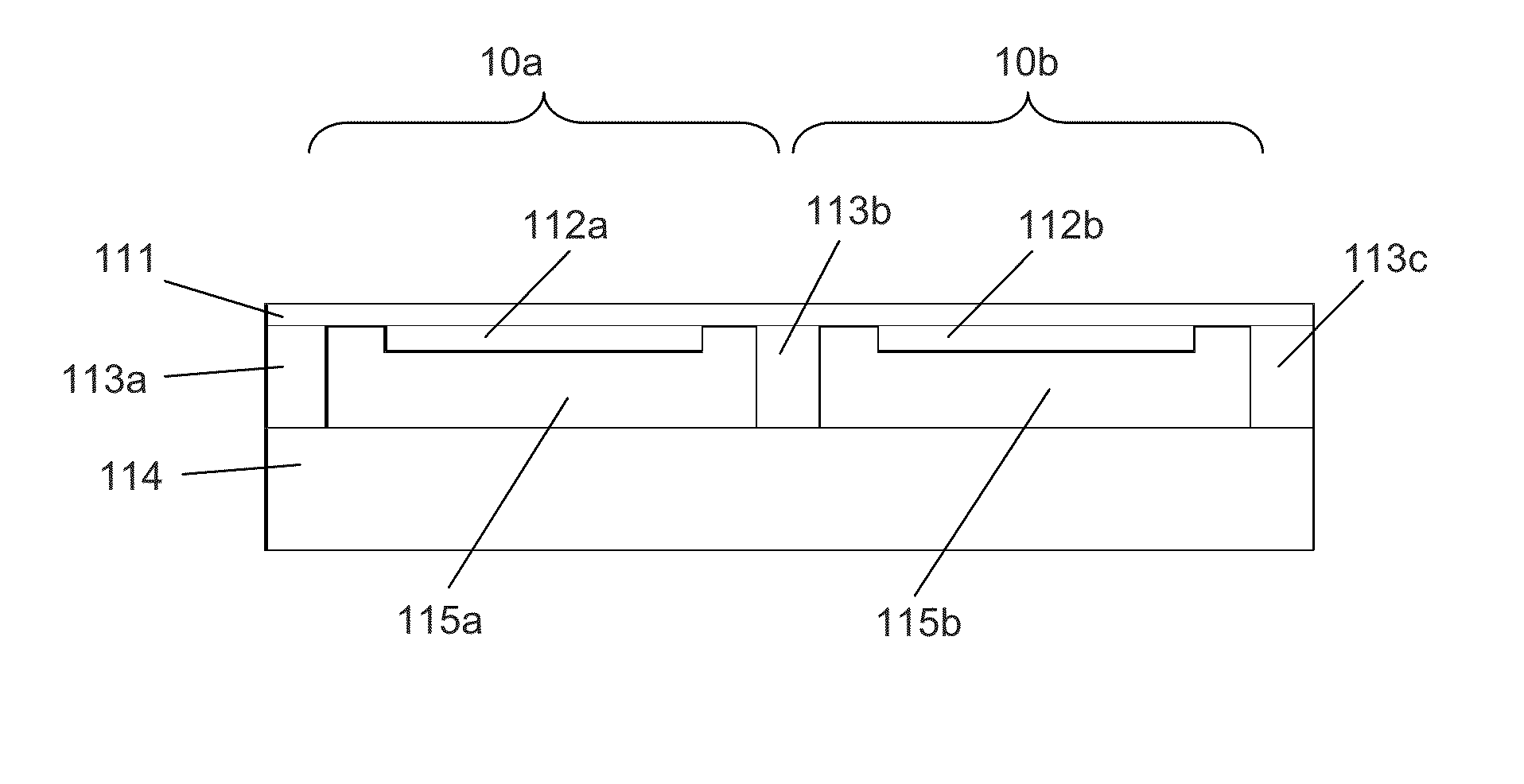
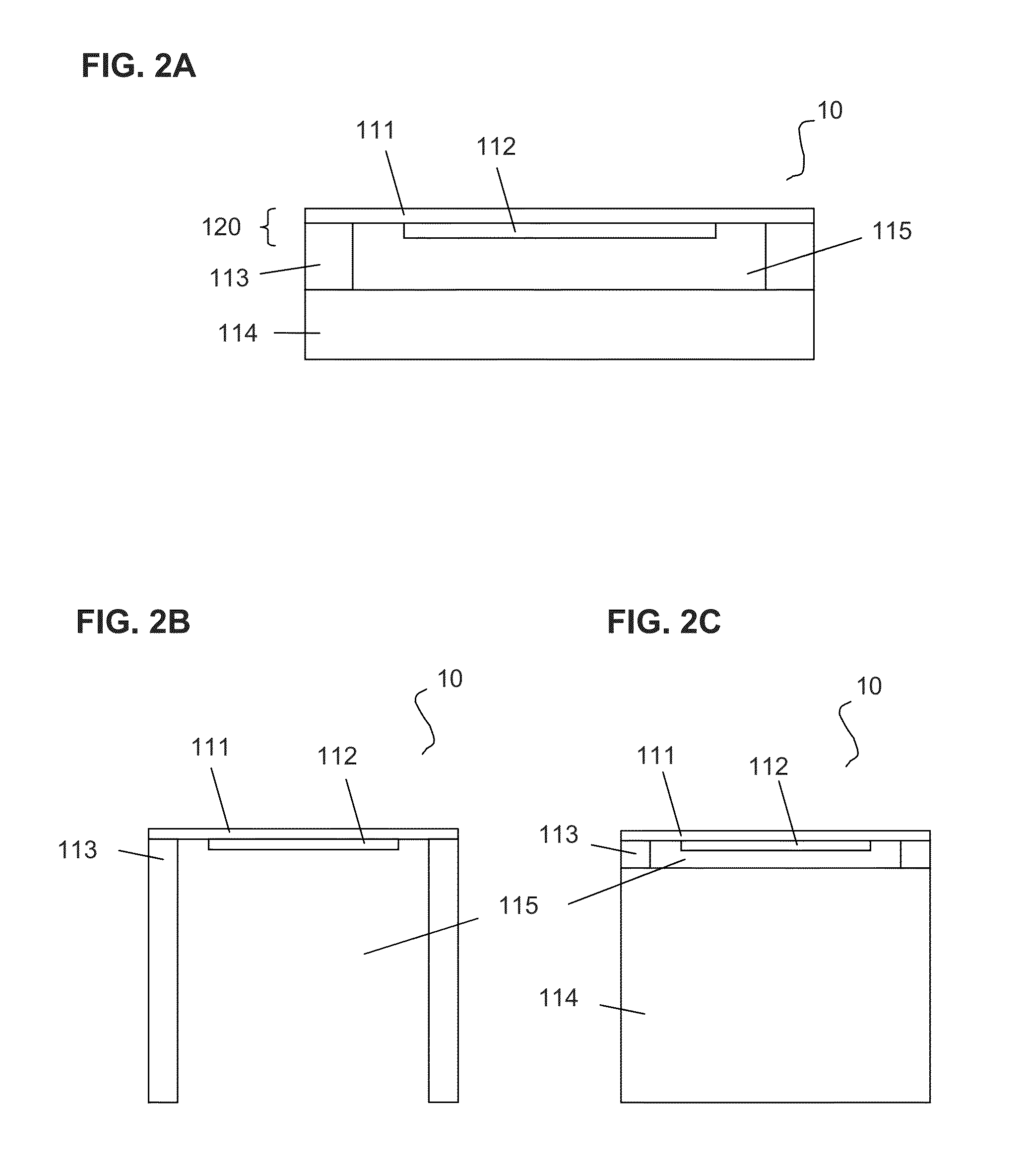
[0041]The present invention provides a multi-cell electroacoustic transducer and a method of fabricating such a transducer. The electroacoustic transducer device of the invention is substantially flat, comprising a plurality of cells in a plane. The transducing component comprises a cell, and each cell may comprise a bilayer unit. Specifically, an array of piezoelectric disks may be attached to a flexural plate, tiled in a plane to provide a matrix of bilayer units (cells). Electrical input to the piezoelectric disks may be supplied via wires. The electro-acoustic cells convert electric signals to ultrasonic acoustic signals, which signals may be directionally emitted with minimal energy loss because of the design of the device. Through the collective effect of the plurality of cells, the transducer device may achieve high transmission sensitivity across a large bandwidth to provide a wide acoustic field. The array also allows for designs that enhance directional properties, which p...


PUM


Abstract

The present invention relates to a transducer device having a planar array of electroacoustic cells, each including a piezoelectric bilayer unit. The transducer device achieves high transmission sensitivity across a broad bandwidth. The transducer device may be designed to have a broad or a focused directivity pattern, or may be multi-frequency, depending on the particular application and has a range of applications. For example, the transducer device may be used with an implanted passive ultrasonically excitable resonating sensor, to excite the sensor and/or to interrogate the sensor, for example in conjunction with Doppler-based analysis of the resonance frequency of the sensor, and/or to locate an implanted sensor. The invention also relates to a method of manufacturing the device.

Description

FIELD OF INVENTION[0001]This invention relates to a novel electroacoustic transducer, in particular a multi-cell transducer, an ultrasonic transmitter incorporating such a multi-cell transducer, and a method of manufacturing such an electroacoustic transducer.BACKGROUND OF THE INVENTION[0002]Electroacoustic transducers convert electrical energy into mechanical oscillations at a frequency in the acoustic range, for example, in the sonic or ultrasonic range, and / or may receive such sound waves and convert the mechanical energy into electrical energy. Such conversion may be achieved by, for example, piezoelectric devices. Piezoelectric devices may have a layered structure, including one or two piezoelectric layers and a flex layer capable of vibrating, which typically is metal but also may be a non-metallic material.[0003]The efficiency of an acoustic transmitter is a function of the radiation and mechanical transduction efficiencies of the device, and the overall efficiency of a singl...

Claims


Application Information

Patent Timeline
Patent Type & Authority Applications(United States)
IPC IPC(8): H01L41/08H01L41/25
CPCH01L41/25H01L41/0825B06B1/0622H10N30/1071H10N30/03H04R17/00
Inventor SAVOIA, ALESSANDRO STUARTCALIANO, GIOSUEMELAMUD, ALEXANDERTAMMAM, ERIC S.
Owner MICROTECH MEDICAL TECH
Why Eureka
Try Eureka