Speaker and diaphragm thereof

a technology of diaphragm and speaker, which is applied in the direction of plane diaphragm, transducer details, electrical transducers, etc., can solve the problems of increasing swaying away, and posing many design limitations in the design of the speaker in these electronic products, so as to save space, the overall thickness of the speaker, and the effect of saving spa

Inactive Publication Date: 2016-01-14
LIU SHIH TUNG +2
View PDF4 Cites 10 Cited by
  • Summary
  • Abstract
  • Description
  • Claims
  • Application Information

AI Technical Summary

Benefits of technology

[0010]In summary, the speaker of the instant embodiment includes the diaphragm that has the magnetic layer. The diaphragm possesses magnetism which is different from the conventional materials such as paper, plastics or metallic materials used for a diaphragm. Furthermore, unlike the conventional positioning of the moving-coil, in which the moving-coil is positioned above a support frame and attached to a diaphragm while a magnetic assembly is positioned below the support frame, the magnetic diaphragm of the instant disclosure is positioned above the support frame while the coil is positioned below the support frame. With the aforementioned design, the speaker in the instant disclosure saves space, in which the magnetic assembly is no longer necessary. In addition, the diaphragm and the coil are spaced apart with a gap which can be as narrow as possible there-between, which is different from the conventional moving-coil where it is necessary to maintain a large enough space for the moving-coil to lead the vibration of the diaphragm. With the magnetic diaphragm and the corresponding coil of the speaker in accordance with the instant disclosure, the overall thickness of the speaker in the instant disclosure effectively reduced to provide a light and thin design, and space is saved that could once be occupied by the conventional magnetic assembly.

Problems solved by technology

Consumer electronic products such as smart phones, smart watches, wristbands, tablets, and notebooks are all trending towards thin appearances and light weight, thus posing much design limitations to the design of speakers in these electronic products.
However, the magnetic assembly of the conventional moving-coil type speakers typically occupies a substantial amount of spaces, and the speakers per se possess an overall bulky body due to the space necessary to allow the moving-coil affixed to the diaphragm to drive the diaphragm axially for sound generation, and the space for magnetic assembly, thus increasing the overall thickness of the speakers and swaying away from the trend of thin appearances and light weight.

Method used


Image

  • Speaker and diaphragm thereof
  • Speaker and diaphragm thereof
  • Speaker and diaphragm thereof

Examples


Embodiment Construction

[0017]The aforementioned illustrations and detailed descriptions are exemplarities for the purpose of further explaining the scope of the instant disclosure. Other objectives and advantages related to the instant disclosure will be illustrated in the subsequent descriptions and appended drawings.

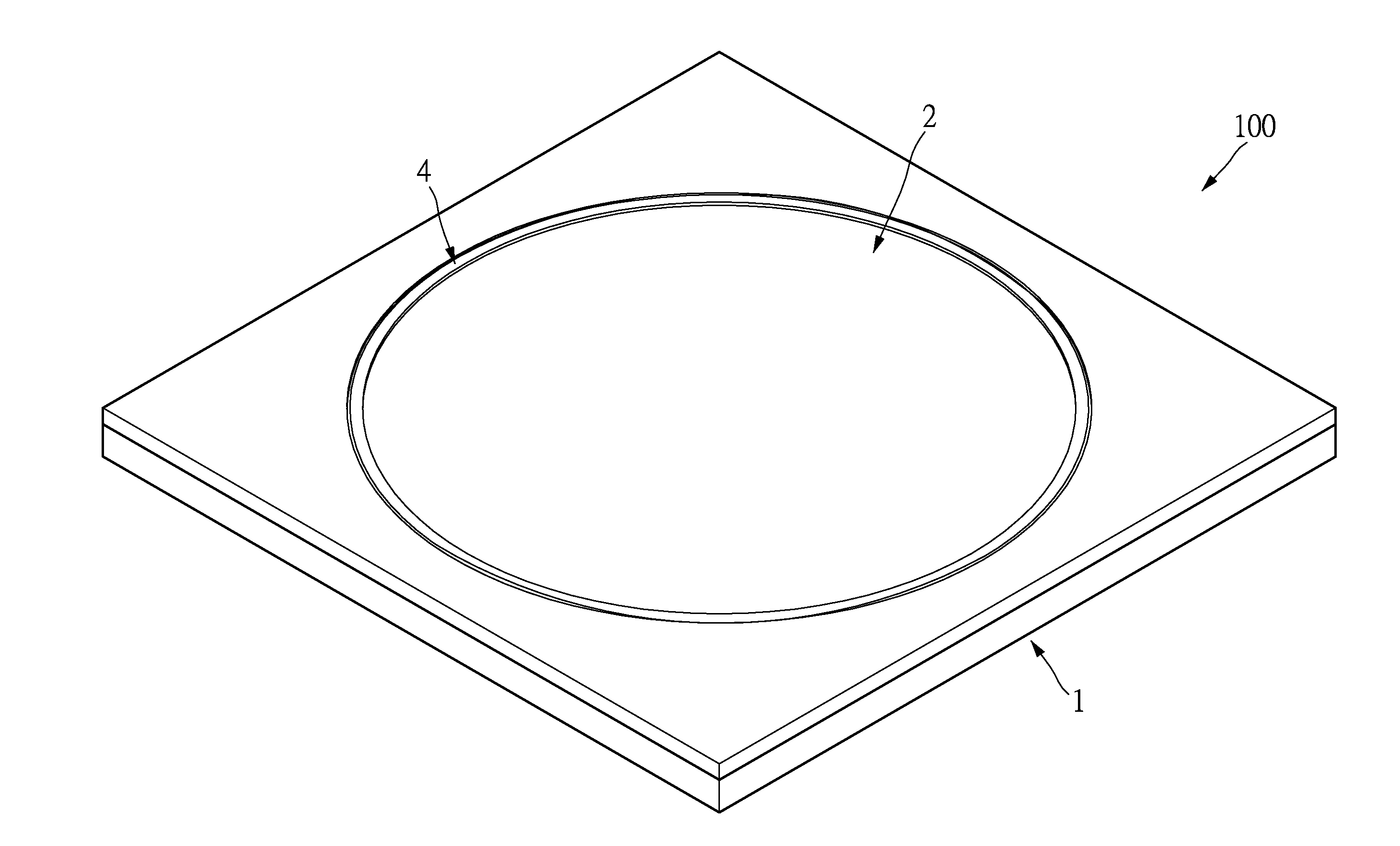
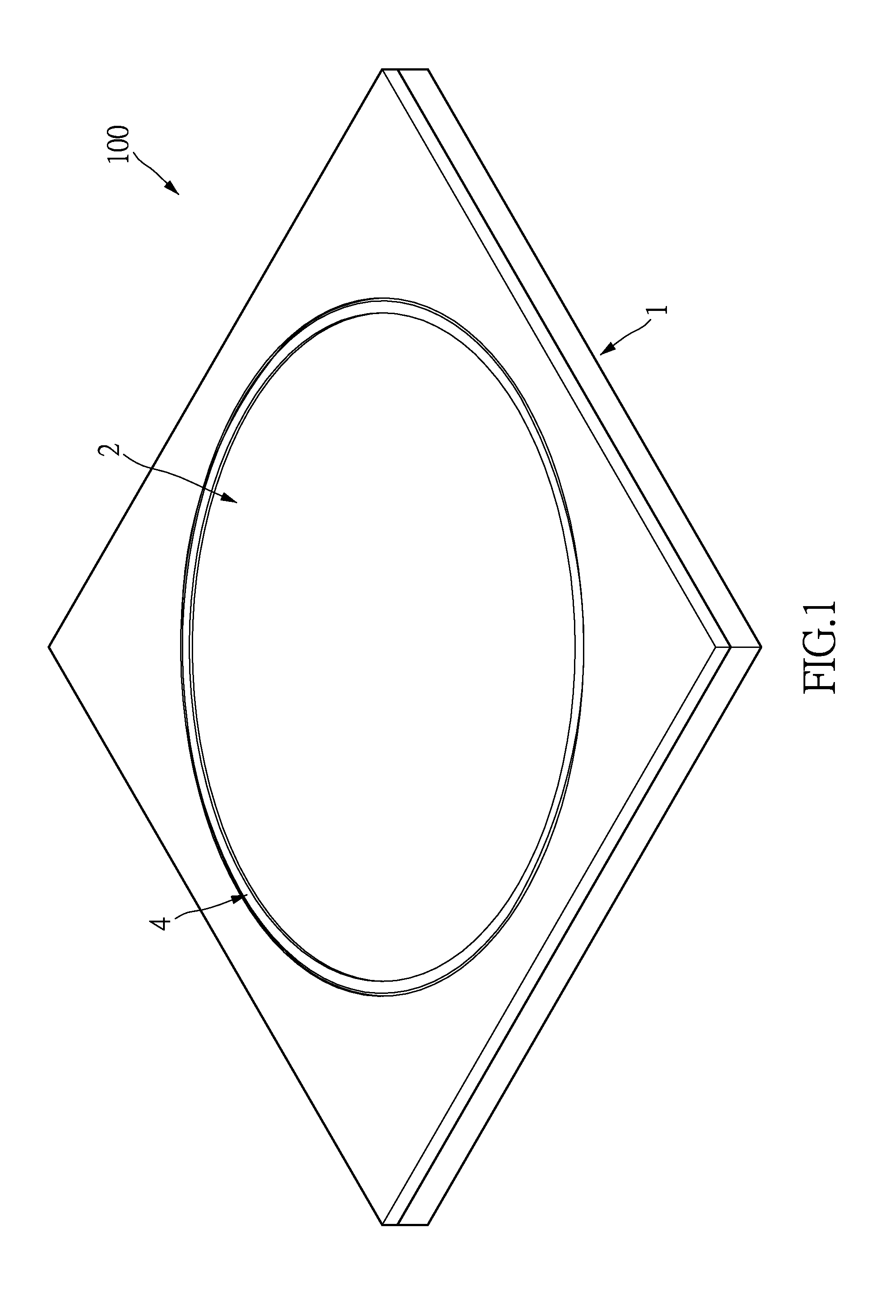
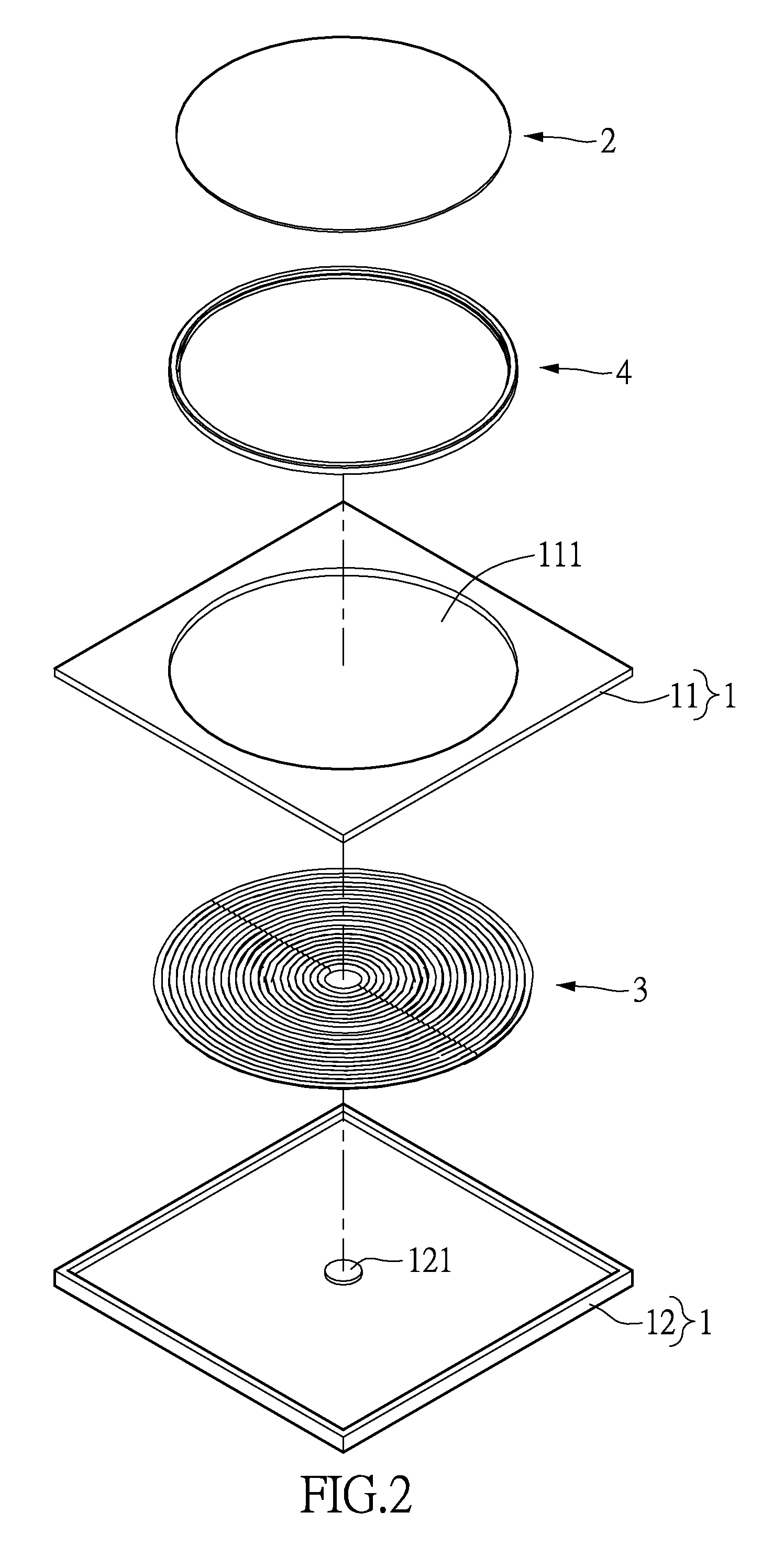
[0018]Please refer to FIGS. 1 to 5 as one embodiment of the speaker in the instant disclosure. As shown in FIGS. 1 and 2, the speaker 100 basically includes a support structure 1, a diaphragm 2, and a coil 3.

[0019]The support structure 1 is made of insulating materials such as plastic and resembles a flat rectangular appearance. The support structure 1 can further disassembled into two portions, an upper frame 11 and a lower frame 12. The upper frame 11 has an opening 111 formed thereon.

[0020]The diaphragm 2 resembles a thin film and is located on the upper frame 11 of the support structure 1 and circumscribed by peripheral portions of the opening 111. As shown in FIGS. 4 and 5, the diaphrag...


PUM


Abstract

The instant disclosure provides a speaker which includes a support structure, a diaphragm, and a coil. The upper frame of the support structure has an opening formed thereon. The diaphragm is disposed on the upper frame of the support structure and located at the peripheral portions of the opening The diaphragm has a substrate layer and a magnetic layer formed thereon. The coil is disposed on the lower frame of the support structure and opposite to the diaphragm. The coil drives the diaphragm to vibrate for sound generation by electromagnetic induction when an electrical current is introduced through the coil.

Description

BACKGROUND OF THE INVENTION[0001]1. Field of the Invention[0002]The instant disclosure relates to a speaker and a diaphragm thereof; in particular, to a thin, light speaker, and a magnetic diaphragm thereof.[0003]2. Description of Related Art[0004]Consumer electronic products such as smart phones, smart watches, wristbands, tablets, and notebooks are all trending towards thin appearances and light weight, thus posing much design limitations to the design of speakers in these electronic products. Typically, moving-coil type speakers are among the most commonly applied speakers in these electronic products. The conventional moving-coil type speakers generate electromagnetic induction to drive the diaphragm for sound generation mainly through the arrangement of moving-coil positioning above and magnetic assembly (inner and outer magnets) below. The specific actuation is provided by disposing moving-coil into a gap between the magnets, introducing a current through the moving-coil such ...

Claims


Application Information

Patent Timeline
Patent Type & Authority Applications(United States)
IPC IPC(8): H04R7/02H04R1/00H04R9/02
CPCH04R7/02H04R9/02H04R1/00H04R7/10H04R13/00H04R2307/021H04R2307/023H04R2307/025H04R2307/027
Inventor LIU, SHIH-TUNG
Owner LIU SHIH TUNG
Why Eureka
Try Eureka