Wheel Loader

a technology of wheel loader and loader, which is applied in the direction of mechanical machines/dredgers, fluid gearings, gearings, etc., can solve the problems of increasing the load, increasing the load, and increasing the load, so as to reduce the engine torque, the effect of reducing the torque generated when the hydraulic drive is switched to the mechanical drive and increasing the torque rapid

Active Publication Date: 2016-01-28
KOMATSU LTD
View PDF4 Cites 20 Cited by
  • Summary
  • Abstract
  • Description
  • Claims
  • Application Information

AI Technical Summary

Benefits of technology

[0023]In the third aspect, in switching from the hydraulic drive state to the mechanical drive state, the fuel injection to the engine is controlled to reduce the engine torque. Therefore, torque generated when the hydraulic drive is switched to the mechanical drive can thus be reduced and a gear shift shock resulting from a rapid torque increase can be avoided. Consequently, the gear shift shock can thus be further reduced.
[0024]In the fourth aspect, the hydraulic pump and the hydraulic motor each have a variable displacement, and at least the displacement of the hydraulic pump is controlled to be zero after the hydraulic drive state is switched to the mechanical drive state. The power consumption of the hydraulic pump during the mechanical drive can be reduced and, consequently, efficiency can be improved.
[0025]In the fifth aspect, in order to switch from the mechanical drive state to the hydraulic drive state during deceleration of the wheel loader in the mechanical drive state, the displacement of the hydraulic pump is set at a value corresponding to the engine speed, the displacement of the hydraulic motor is adjusted to make the motor speed of the hydraulic motor become a value corresponding to the discharge amount of the hydraulic pump and the vehicle speed, and engages the hydraulic drive clutch when a difference between rotation speeds before and after the hydraulic drive clutch reaches a threshold or less and disengages the mechanical drive clutch when a pressure of the hydraulic oil delivered from the hydraulic pump to the hydraulic motor increases to a predetermined value or more. A gear shift shock during a deceleration process for switching from the mechanical drive to the hydraulic drive can thus be reduced, so that the mechanical drive can be smoothly switched to the hydraulic drive. Consequently, a load in the bucket can be prevented from falling off during deceleration, thereby improving efficiency and reducing fuel consumption.
[0026]In the sixth aspect, the motor speed of the hydraulic motor is increased before the mechanical drive state is switched to the hydraulic drive state during deceleration of the wheel loader in the mechanical drive state. Therefore, when the clutch is engaged to connect the hydraulic drive unit to the output shaft rotated in the mechanical drive unit, a difference between rotation speeds on the upstream and downstream of the clutch can be reduced to smoothly switch to the hydraulic drive state.
[0027]In the seventh aspect, each of the mechanical drive clutch and the hydraulic drive clutch is a modulation clutch. Therefore, for instance, a controlling hydraulic pressure is controlled based on a variation pattern defined as a modulation pattern, so that the clutch is temporarily set in a so-called semi-clutch state (an interim value of the engagement ratio) to reduce a gear shift shock.
[0028]In the eighth aspect, the mechanical drive unit is used only when the wheel loader travels forward, and the wheel loader reverses only using the hydraulic drive unit. Therefore, a mechanical drive switching clutch for reverse, which causes a large loss during a forward travel, may be omitted and, consequently, efficiency can be improved.

Problems solved by technology

However, HST entails a problem of a decrease in efficiency during a high-speed operation.
Therefore, when the vehicle, which may be a wheel loader or a backhoe loader, has to travel a certain amount of distance to a dump truck or a hopper with a load in the bucket, a decrease in efficiency is inevitable.
However, since a wheel-type excavator or the like is not designed to travel with a load in the bucket, a problem that a load may fall due to a switching shock resulting from the switching from hydraulic drive to mechanical drive is not typically taken into account.

Method used


Image

  • Wheel Loader
  • Wheel Loader
  • Wheel Loader

Examples


Embodiment Construction

)

[0040]Exemplary embodiment(s) of the invention will be described below with reference to the attached drawings.

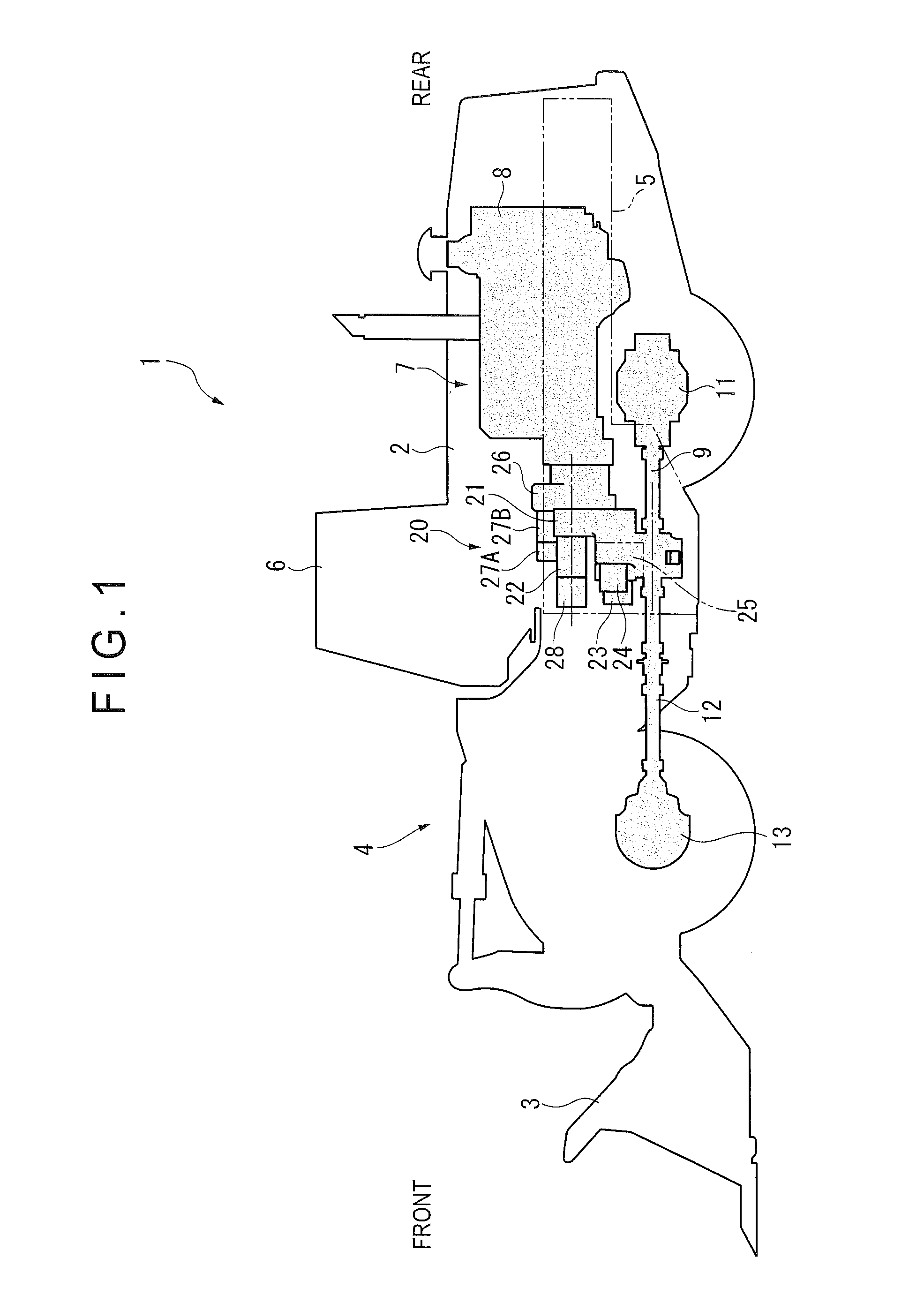
[0041]FIG. 1 is a transparent view schematically illustrating a wheel loader 1 according to an exemplary embodiment and a power transmission system thereof for traveling. It should be noted that directions of front, rear, right and left hereinafter mean directions of front, rear, right and left from an operator seated in a cab 6 shown in FIG. 1.

Overall Arrangement of Wheel Loader

[0042]As shown in FIG. 1, the wheel loader 1 is substantially the same as a typical wheel loader except, for instance, an arrangement of a transmission 20 (described later) and appearance. Specifically, the wheel loader 1 includes: a vehicle body 2 including a front vehicle body and a rear vehicle body; and a bucket 3, which is working equipment for excavation and loading, attached to a front side of the front vehicle body through a hydraulic working equipment drive mechanism 4 including, for insta...


PUM


Abstract

A wheel loader includes: a mechanical drive unit; a mechanical drive clutch controlling transmission/cutoff of a power in the mechanical drive unit; an HST pump driven by an engine; a hydraulic motor driven by a hydraulic oil delivered from the HST pump; a hydraulic drive unit; a hydraulic drive clutch controlling transmission/cutoff of a power in the hydraulic drive unit; a load detecting unit detecting an amount of a load; a vehicle speed sensor detecting a vehicle speed; a switching controlling unit setting a switching vehicle speed in accordance with the amount of the load; and a vehicle-body controller switching between mechanical drive state and hydraulic drive state based on the switching controlling unit. The switching controlling unit sets the switching vehicle speed at a high-speed side when the load becomes large and at a low-speed side when the load becomes small.

Description

TECHNICAL FIELD[0001]The present invention relates to a wheel loader including a backhoe loader. In particular, the present invention relates to a wheel loader provided with a transmission capable of switching between hydraulic actuation and mechanical actuation.BACKGROUND ART[0002]Some wheel loaders are provided with a so-called hydro static transmission (HST) so that a hydraulic pump is driven by an engine output and a traveling hydraulic motor is driven by a hydraulic oil discharged from the hydraulic pump for the traveling of the vehicle.[0003]Some wheel-type excavators, rough terrain cranes and the like employ a hydraulic mechanical transmission (HMT) system including a combination of HST and mechanical transmission (see, for instance, Patent Literature 2).[0004]According to Patent Literature 2, hydraulic drive is automatically selected when a measured rotation speed of an output shaft is a predetermined value or less, whereas mechanical drive is automatically selected when the...

Claims


Application Information

Patent Timeline
Patent Type & Authority Applications(United States)
IPC IPC(8): E02F9/22E02F3/34E02F3/42E02F9/20
CPCE02F9/2253E02F3/34E02F9/2062E02F9/2296E02F3/422E02F9/2079F16H47/04F16H2200/2005F16H2037/0886F16H47/02F16H61/421F16H61/431F16H61/462B60Y2200/415F16H61/0437F16H2047/045F16H47/10F16H61/66F16H61/02F16H61/04
Inventor KOBIKI, YASUHIRO
Owner KOMATSU LTD
Why Eureka
Try Eureka