Electrothermal composite material and electrothermal actuator using the same
a technology of electrothermal composite materials and composite materials, applied in the direction of machines/engines, other domestic articles, synthetic resin layered products, etc., can solve the problems of slow response rate of conventional electrothermal composite materials and beneficial to practical application
- Summary
- Abstract
- Description
- Claims
- Application Information
AI Technical Summary
Benefits of technology
Problems solved by technology
Method used
Image
Examples
first embodiment
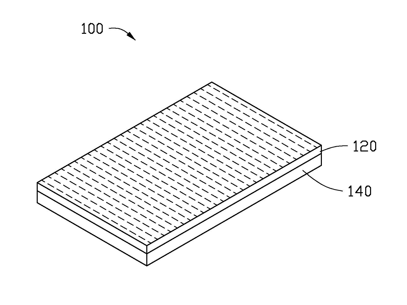
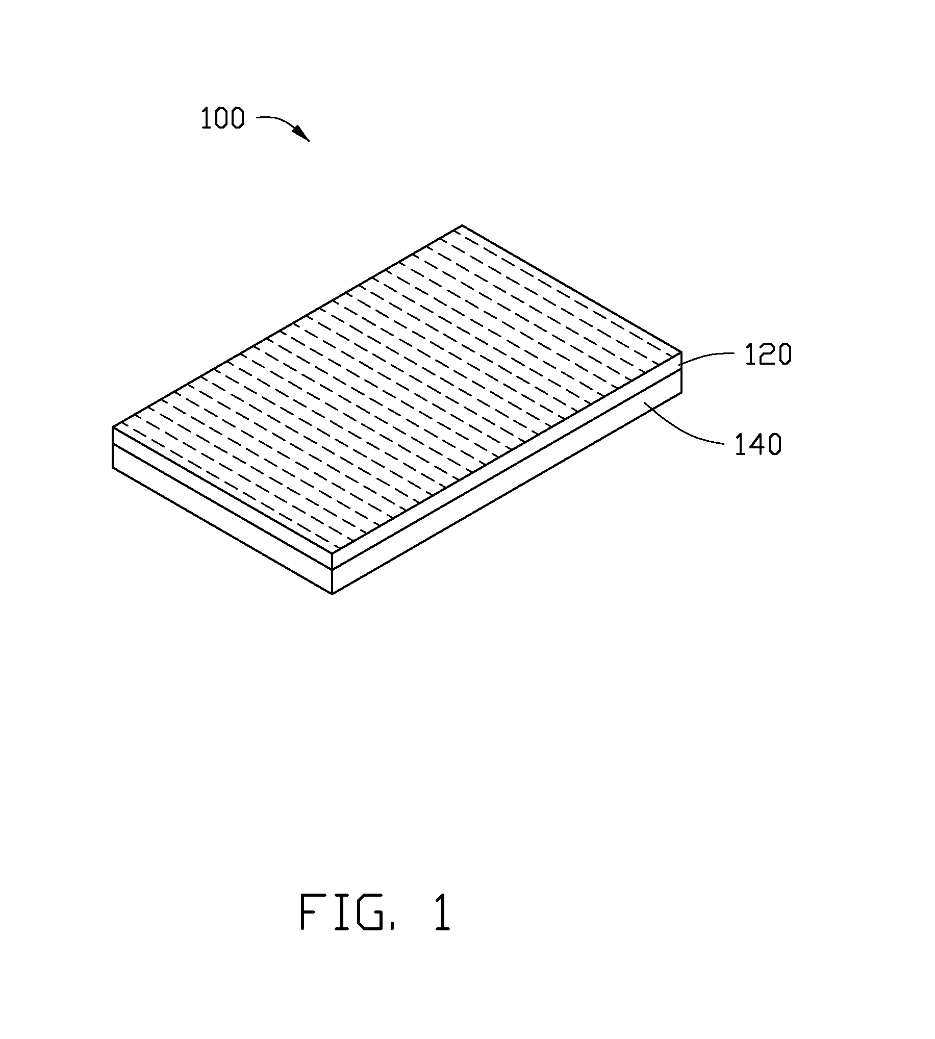
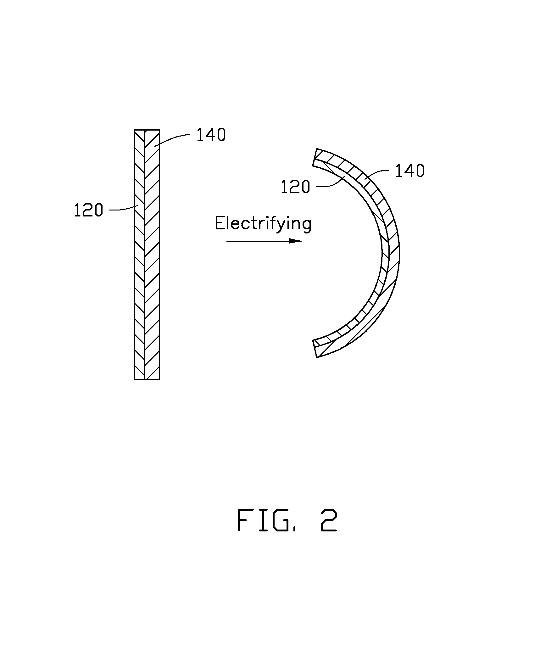
[0022]Referring to FIG. 1, an electrothermal composite material 100 includes a flexible polymer layer 140 and a carbon nanotube paper 120. The carbon nanotube paper 120 is stacked on the flexible polymer layer 140 and at least partly embedded into the flexible polymer layer 140. A thermal expansion coefficient of the carbon nanotube paper 120 is greater than or equal to ten times that of the flexible polymer layer 140. In one embodiment, the thermal expansion coefficient of the carbon nanotube paper 120 is greater than or equal to one hundred times that of the flexible polymer layer 140.
[0023]A thickness of the carbon nanotube paper 120 is in a range from about 30 micrometers to about 50 micrometers. A conductivity of the carbon nanotube paper 120 along a first direction parallel to a surface of the carbon nanotube paper 120 is in a range from about 1000 S / m to about 6000 S / m. When the conductivity of the carbon nanotube paper 120 along the first direction is too large, such as grea...
second embodiment
[0030]Referring to FIG. 3, an electrothermal actuator 10 includes an operating portion 102 and two electrodes 112. The operating portion 102 is a long strip formed by cutting the electrothermal composite material 100. The operating portion 102 at least partially extends along the first direction. The extending direction of the plurality of carbon nanotubes is substantially perpendicular to a longitudinal direction of the operating portion 102. The conductivity of the operating portion 102 along the longitudinal direction is about 3000 S / m, and the conductivity of the operating portion 102 along the extending direction of the plurality of carbon nanotubes is about 30000 S / m. An extending direction of the two electrodes 112 is substantially perpendicular to the longitudinal direction of the operating portion 102. The two electrodes 112 are parallel to and spaced apart from each other. The two electrodes 112 can be located on opposite ends of the operating portion 102 along the longitu...
third embodiment
[0033]Referring to FIG. 4, an electrothermal actuator 20 includes two operating portions 202 and two electrodes 212. The two operating portions 202 are connected with each other to form an L-shaped structure with a conductive path, wherein each operating portions 202 is a long strip obtained by cutting the electrothermal composite material 100. The two electrodes 212 are respectively located on two ends of the L-shaped structure and electrically connected with the conductive path. Thus, a current can be introduced to the L-shaped structure via the two electrodes 212.
[0034]Each of the two operating portions 202 includes a plurality of carbon nanotubes extending substantially along the same direction and joined end-to-end by Van der Waals attractive force in the extending direction. An angle between the extending direction of the plurality of carbon nanotubes and a current direction is about 45°. Thus, a conductivity of each operating portions 202 along the current direction is in a r...
PUM
| Property | Measurement | Unit |
|---|---|---|
| Time | aaaaa | aaaaa |
| Thickness | aaaaa | aaaaa |
| Thickness | aaaaa | aaaaa |
Abstract
Description
Claims
Application Information
 - R&D
- Intellectual Property
- Life Sciences
- Materials
- Tech Scout
- Unparalleled Data Quality
- Higher Quality Content
- 60% Fewer Hallucinations
Browse by: Latest US Patents, China's latest patents, Technical Efficacy Thesaurus, Application Domain, Technology Topic, Popular Technical Reports.
© 2025 PatSnap. All rights reserved.Legal|Privacy policy|Modern Slavery Act Transparency Statement|Sitemap|About US| Contact US: help@patsnap.com


