Aircraft with a framework structure that comprises at least one hollow frame

a technology of aircraft frame and frame structure, which is applied in the direction of fuselage, transportation and packaging, energy-saving board measures, etc., can solve the problems of reducing the already limited available space in the aircraft, requiring a comparatively large number of interconnected components, and unable to use space for other purposes, so as to improve the air conditioning and/or ventilating system

Active Publication Date: 2016-02-04
AIRBUS HELICOPTERS DEUT GMBH
View PDF62 Cites 10 Cited by
  • Summary
  • Abstract
  • Description
  • Claims
  • Application Information

AI Technical Summary

Benefits of technology

[0019]It is, therefore, an object of the present invention to provide a new aircraft with an improved air conditioning and / or ventilating system.

Problems solved by technology

However, such flexible hoses, tubes and / or pipes require a certain installation space that must be allocated and reserved in the aircraft.
This installation space cannot be used for other purposes and, thus, further reduces an already limited available space in the aircraft.
This aircraft air conditioning system, however, requires a comparatively large number of interconnected components.
Accordingly, assembly of the aircraft air conditioning system is time-consuming and, therefore, expensive.
Furthermore, due to the comparatively large number of interconnected components, this aircraft air conditioning system is prone to air leakage, leading to a reduced overall performance of the system.
However, the intersecting points where the longitudinal frames, transverse frames and transverse beams are respectively interconnected are prone to air leakage, as they would normally not fit perfectly to each other due to underlying manufacturing tolerances.
Accordingly, the generated air stream that moves e.g. from an air duct in a longitudinal frame via an intersecting point into a transversal frame or beam would potentially leak at the intersecting point, therefore limiting the overall achievable performance of the air conditioning system.
Furthermore, this lattice structure is not suitable for implementing an air conditioning or ventilating system in a cockpit region of an aircraft, which is structurally a very complex region, where generally no interconnectable longitudinal and transversal frames and / or beams exist.
However, all of the above described air duct systems are more or less prone to air leakage.
Furthermore, they are not suitable for implementing an air conditioning or ventilating system in an aircraft with reduced installation space requirements permitting its installation e.g. in a cockpit region of the aircraft, which inherently exhibits only limited available space

Method used


Image

  • Aircraft with a framework structure that comprises at least one hollow frame
  • Aircraft with a framework structure that comprises at least one hollow frame
  • Aircraft with a framework structure that comprises at least one hollow frame

Examples


Embodiment Construction

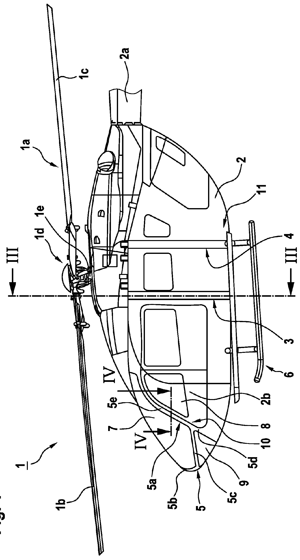
[0058]FIG. 1 shows an aircraft 1 according to one aspect of the invention, which comprises a fuselage 2 having a framework structure 5 with at least one hollow frame 5a. Illustratively, the fuselage 2 is connected to a landing gear 6 and defines, by way of example, at least a tail boom 2a and a cockpit 2b. For simplicity and clarity of the drawings, the tail boom 2a is cut away and not shown in greater detail.

[0059]The aircraft 1 is exemplarily embodied as a rotary-wing aircraft and, in particular, as a helicopter. Therefore, the aircraft 1 is also referred to hereinafter as the “helicopter 1” for simplicity and clarity. It should, however, be noted that the present invention is not limited to helicopters and can likewise be applied to other aircrafts having a fuselage that comprises a framework structure with at least one hollow frame according to the invention.

[0060]The helicopter 1 illustratively comprises at least one multi-blade main rotor 1a for providing lift and forward or b...


PUM


Abstract

An aircraft with a fuselage that comprises a framework structure having at least one hollow frame that is integrally formed in one piece and comprises fiber reinforced polymers, the at least one hollow frame defining an integrated ventilation air duct that is adapted for guiding ventilation air into the aircraft.

Description

CROSS REFERENCE TO RELATED APPLICATION[0001]This application claims priority to European patent application No. EP 14 400041.1 filed on Jul. 30, 2014, the disclosure of which is incorporated in its entirety by reference herein.BACKGROUND OF THE INVENTION[0002](1) Field of the Invention[0003]The invention is related to a rotary wing aircraft with a fuselage that comprises a framework structure having at least one hollow frame.[0004](2) Description of Related Art[0005]A fuselage of an aircraft, and in particular of a rotorcraft, can at least partly be provided with a framework structure having one or more hollow frames in order to reduce an overall weight of the fuselage. Usually, such hollow frames consist of a plurality of hollow frame beams that are separately manufactured and subsequently assembled to define the framework structure. To this end, these separate hollow frame beams are interconnected during assembly at corresponding intersection points by means of suitable joints.[00...

Claims


Application Information

Patent Timeline
Patent Type & Authority Applications(United States)
IPC IPC(8): B64C1/06B64D13/00
CPCB64C1/061B64D13/00B64C27/04B64C2001/0072B64D2013/003B64D2013/0625B64D13/06Y02T50/40Y02T50/50B64D13/08
Inventor MORES, SEBASTIANBARNERSSOI, JOHANNPROBST, STEFANSCHNEEBERGER, MARCOJUTT, HARTMUT
Owner AIRBUS HELICOPTERS DEUT GMBH
Why Eureka
Try Eureka