
Closed-cycle plant

Active Publication Date: 2016-02-04
ELETTROMECCANICA VENETA
View PDF6 Cites 19 Cited by
  • Summary
  • Abstract
  • Description
  • Claims
  • Application Information

AI Technical Summary

Benefits of technology

The patent relates to a plant using a Rankine cycle that can adapt to different working conditions to maximize power output with high efficiency. The plant should require little maintenance, be compact and easy to install with low production and assembly costs. The patent also introduces a process to effectively utilize the plant.

Problems solved by technology

As it is known, heat sources are widely available, particularly at a low / medium temperature, which are now dispersed in the environment, and therefore wasted.
De facto, the conversion of the heat supplied by said sources into electric power is, by the nowadays available recovering and converting means and processes, too expensive in relation with the power produced.
Therefore, such sources, even though are used in a limited way for professional applications, are scarcely used by the people, and particularly in the domestic environment.
However, such solution has some constraints and disadvantages which are well known to the person skilled in the art, and which are:high cost of the turbine and of the associated control elements;necessity of a frequent maintenance with following duties of different type;maximum efficiency which is only obtained at a precisely determined flow rate of the expanding fluid and at a defined rotation speed; specifically, this is perhaps the greatest limitation of the turbine systems because if the rotation speed is affected by a slight variation with respect to the optimal value, the turbine efficiency drastically drops.
For the above mentioned reasons, it is absolutely evident that the steam turbines are not very suitable for harnessing medium / low temperature thermal sources and having an extremely variable thermal supply (as indicated in the above exemplified examples) and therefore not very suitable for small-sized plants (having a supplied electric power less than 50 KW, for example).

Method used


Image

  • Closed-cycle plant
  • Closed-cycle plant
  • Closed-cycle plant

Examples


Embodiment Construction

General Embodiment of a Closed Cycle Plant for Producing Electric Power

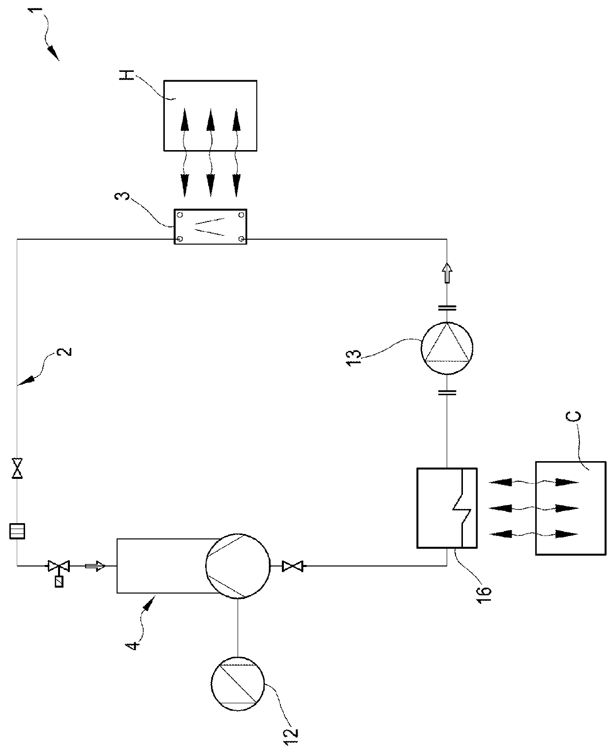
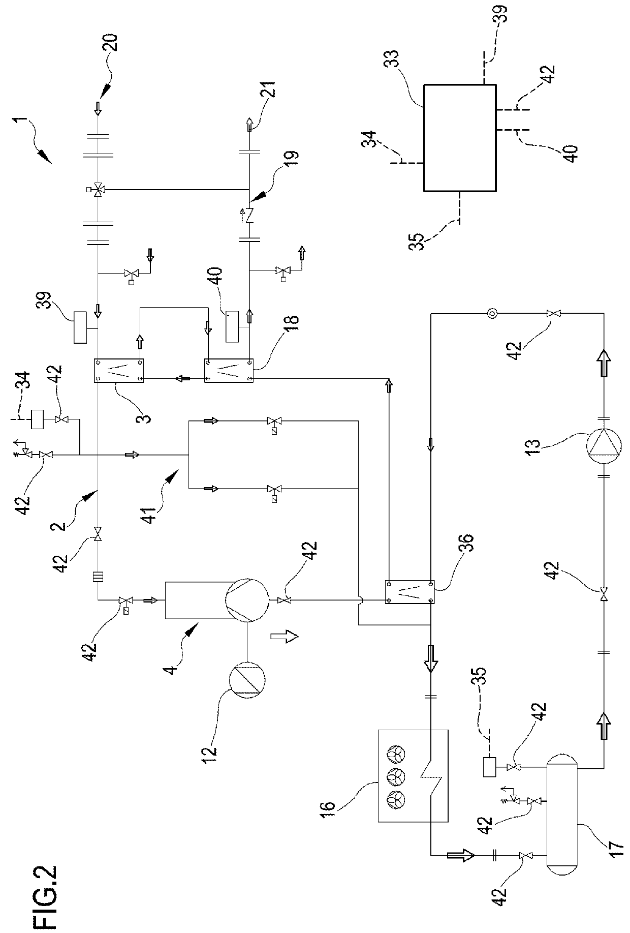
[0112]With 1 has been generally indicated a closed cycle plant, particularly a Rankine cycle, for converting thermal power in electric power. The plant 1 finds, for example, application in biogas / biomass plants for recovering waste heat of a cogeneration process, in geothermal plants for harnessing medium / small heat sources, in industrial plants for recovering heat waste (conversion of heat waste from industrial processes), in the domestic environment for producing electric power and harnessing the heat for sanitary use. A further use of the plant 1 can regard both domestic and industrial systems, wherein the heat source is provided by systems absorbing solar power. Further applications of the plant in the automotive field, for example for recovering heat from the engine (water and / or fumes), are provided.

[0113]As it is visible in FIG. 1, the plant 1 comprises a closed circuit 2 inside which a working fluid circu...


PUM


Abstract

A closed cycle plant for converting thermal power to mechanical or electrical power including: a closed circuit inside which a working fluid circulates according to a predetermined circulation direction, a volumetric expander configured to receive at the inlet the working fluid in a gaseous state. The volumetric expander includes: a jacket having an inlet and an outlet for enabling the introduction and discharge the working fluid; an active element housed in said jacket and suitable for defining, in cooperation with said jacket, a variable volume expansion chamber; a main shaft; a valve active that opens and closes the inlet and outlet, and a generator connected to the main shaft. The valve includes a regulation device configured to vary the duration of the introduction condition, or the maximum through cross-section of the inlet.

Description

FIELD OF THE INVENTION[0001]The present invention refers to a plant, for example a Rankine cycle plant, for generating electric and / or mechanical power by recovering and converting heat.[0002]The present invention can find an application for example in biogas / biomass plants for recovering waste heat of a cogeneration process, in geothermal plants for harnessing medium / small heat sources, in industrial plants for recovering waste heat (by converting the waste heat of the industrial processes), in the domestic environment for producing electric power and harnessing the heat for sanitary use. A further use of the plant can refer to systems, both domestic and industrial systems, wherein the heat source is provided by plants absorbing solar power. Further, it is possible to provide applications of the plant in the automotive field, for example for recovering the heat from the engine (water and / or fumes).BACKGROUND OF THE INVENTION[0003]As it is known, heat sources are widely available, p...

Claims


Application Information

Patent Timeline
IPC IPC(8): F01K15/00F01K11/02F01K23/10
CPCF01K15/00F01K23/10F01K11/02F01K13/02F01K25/08F01L15/08F01L33/02
Inventor ZAMPIERI, GINO
Owner ELETTROMECCANICA VENETA
Learn More