Parallel monitoring circuit for capacitor

a monitoring circuit and capacitor technology, applied in the direction of capacitor propulsion, battery/fuel cell control arrangement, electric devices, etc., can solve the problems of unpredictability of operation and device damage, and achieve the effect of high voltage resistan

Inactive Publication Date: 2016-02-04
FUJI ELECTRIC CO LTD
View PDF2 Cites 18 Cited by
  • Summary
  • Abstract
  • Description
  • Claims
  • Application Information

AI Technical Summary

Benefits of technology

[0029]In accordance with the present invention, the equalization charging of a plurality of capacitors connected in series can be performed to an unrestricted desired value, without using a special comparator of an input rail-to-rail type or a comparator and an operational amplifier with a high voltage resistance.

Problems solved by technology

Therefore, where the input voltage is the same as the power supply voltage, unpredictable operation occurs and the device can be damaged.

Method used


Image

  • Parallel monitoring circuit for capacitor
  • Parallel monitoring circuit for capacitor
  • Parallel monitoring circuit for capacitor

Examples


Embodiment Construction

[0034]An embodiment of the present invention will be explained hereinbelow with reference to the drawings.

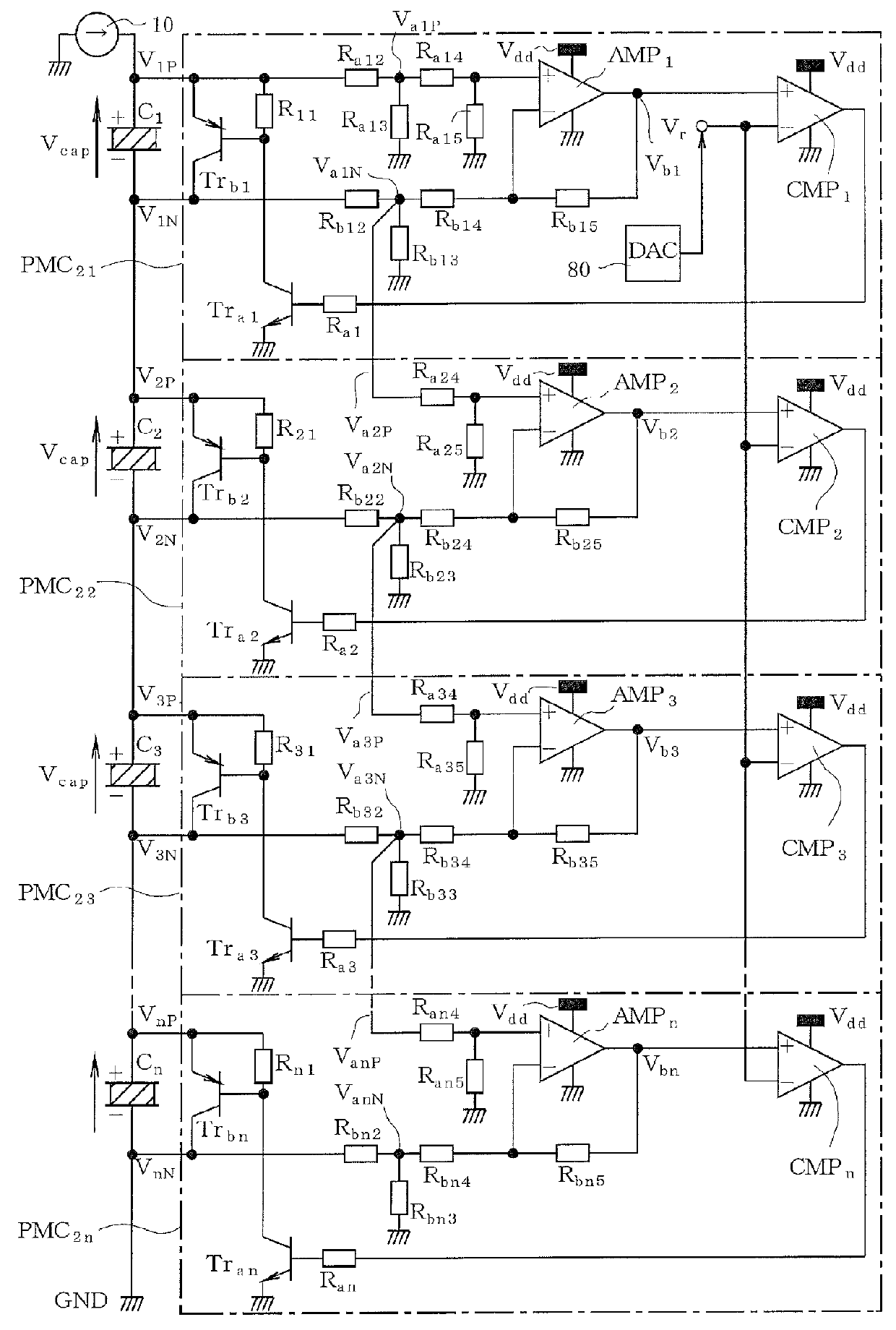
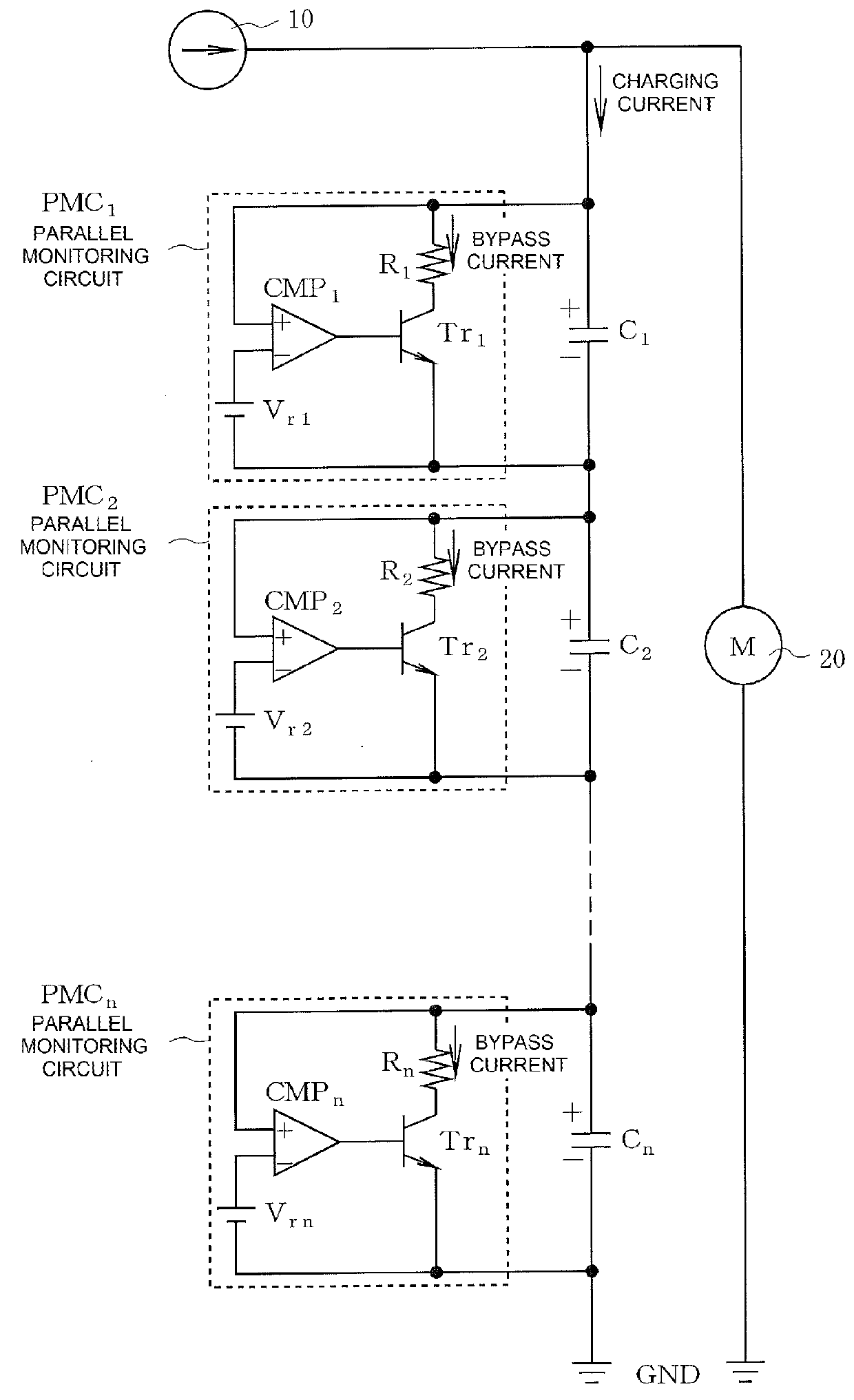
[0035]FIG. 1 is a circuit diagram of a parallel monitoring circuit according to one embodiment of the invention. In FIG. 1, capacitors such as electrical double layer capacitors C1, C2, C3, . . . , Cn are connected in series between a charging current source 10 and the GND (ground), and parallel monitoring circuits PMC21, PMC22, PMC23, . . . , PMC2n are connected to both ends of the respective capacitors C1, C2, C3, . . . , Cn.

[0036]In this configuration, the charge potentials of all of the capacitors C1, C2, C3, . . . , Cn are to be controlled to the same value by the operation of the parallel monitoring circuits PMC21, PMC22, PMC23, . . . , PMC2n.

[0037]Since the parallel monitoring circuits PMC21, PMC22, PMC23, . . . , PMC2n have substantially the same configuration, the configuration thereof is explained hereinbelow by considering mainly the parallel monitoring circuit PMC21 ...


PUM


Abstract

A capacitor charging-discharging system, including a plurality of serially connected capacitors, a voltage source for setting an equalization potential, and a plurality of parallel monitoring circuit. Each parallel monitoring circuit is connected to the two ends electrodes of one capacitor, and includes: a voltage dividing circuit configured to resistively divide and attenuate two voltages respectively on the two end electrodes of the one capacitor, a differential amplifier configured to amplify a difference between the two divided voltages to thereby detecting a charge potential of the one capacitor, a comparator configured to compare the charge potential with the equalization potential, and a charge current bypass circuit configured to control charge current of the one capacitor, based on an output of the comparator, so that the charge potential of the one capacitor matches the equalization potential.

Description

CROSS-REFERENCE TO RELATED APPLICATIONS[0001]This application is a continuation application under 35 U.S.C. §120 of International Application PCT / JP2013 / 076008 having the International Filing Date of Sep. 26, 2013. The identified application is fully incorporated herein by reference.BACKGROUND OF THE INVENTION[0002]1. Technical Field[0003]The present invention relates to a parallel monitoring circuit that is connected in parallel with a corresponding capacitor from a plurality of capacitors connected in series, and that controls the charging current thereof to equalize the charge potentials of the capacitors.[0004]2. Background Art[0005]A capacitor charge-discharge system disclosed in Japanese Patent Application Publication No. 2008-271722 (hereinafter “JPAP'722”; see, e.g., paragraphs [0016] to [0019] and FIG. 1 of JPAP'722) is known as the conventional means for equalizing a charge potential of a plurality of electrical double layer capacitors connected in series.[0006]FIG. 2 is a...

Claims


Application Information

Patent Timeline
Patent Type & Authority Applications(United States)
IPC IPC(8): H02J7/00
CPCH02J7/007H02J7/0068H02J7/0052H02J7/0016H02J7/345B60L3/12B60L2240/547B60L2240/549B60L50/40B60L58/22H02J2310/48Y02T10/70H02J7/0014H02J7/0048B60L3/0046H02J7/00
Inventor HAMADA, YOSHITAKA
Owner FUJI ELECTRIC CO LTD
Why Eureka
Try Eureka