

Drive unit including terminals in resiliant contact with each other
a technology of resiliant contact and drive unit, which is applied in the direction of supporting/enclose/casing, basic electric elements, dynamo-electric machines, etc., can solve the problems of low robustness of the connection between the substrate and the terminal, and no substantial tolerance for the positioning of the terminal, and achieve high assembly accuracy
- Summary
- Abstract
- Description
- Claims
- Application Information
AI Technical Summary
Benefits of technology
Problems solved by technology
Method used
Image

Examples
first embodiment
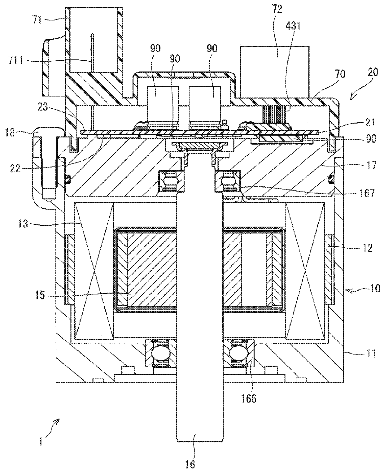
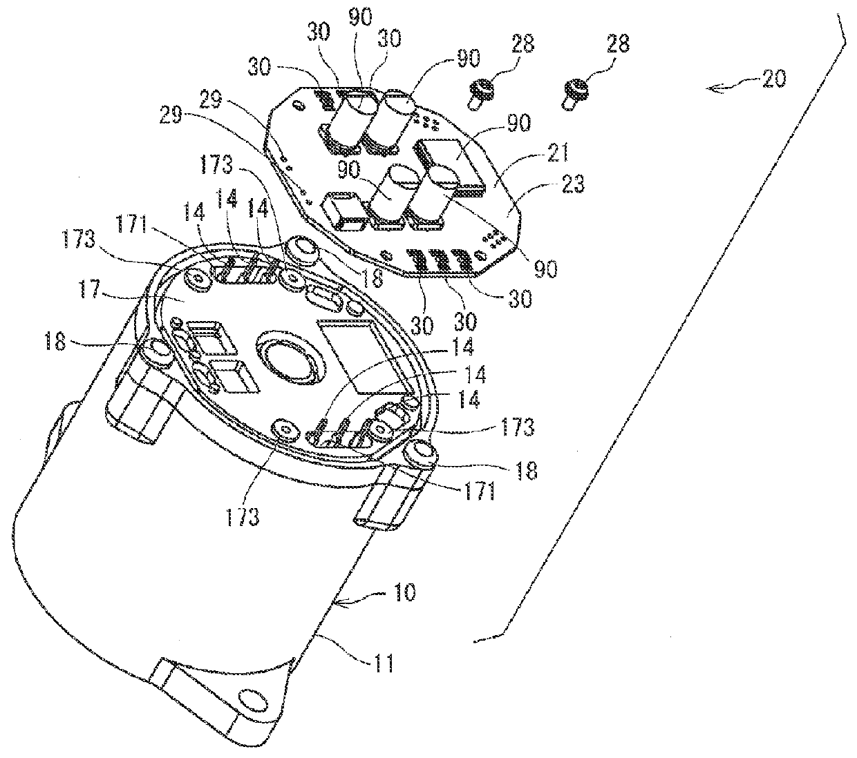
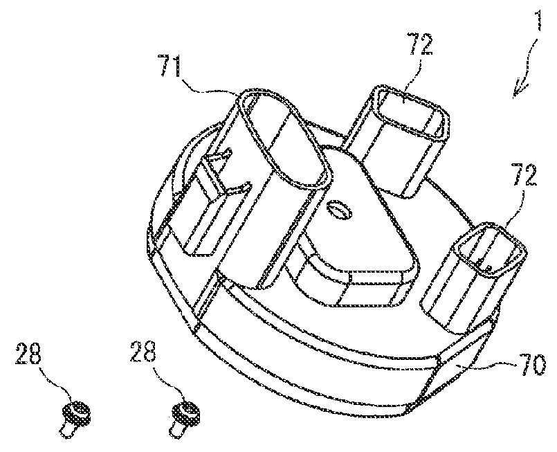
[0029]A drive unit 1 in the first embodiment of the present disclosure is shown in FIGS. 1-5. The drive unit 1 of the present disclosure is applied to an electric power steering device for assisting a steering operation by a driver, for example, and outputs a steering assist torque.
[0030](Configuration of the Drive Unit 1)
[0031]First, the configuration of the drive unit 1 is described with reference to FIGS. 1 and 2.
[0032]The drive unit 1 has a motor 10, which is a rotating electric machine, and an Engine Control Unit (ECU) 20, which is a controller for controlling a drive of the motor 10, combined to have one body.
[0033]The motor 10 is a three-phase brushless motor, and is provided with a motor case 11, a stator 12, winding groups 13 in two sets, a rotor 15, a shaft 16, a frame 17 and the like. The axis of the motor 10 may be used as a reference, such as an axial direction in the following, and a radius of the motor 10 may also be used as a reference, such as a radius direction.
[00...
second embodiment
[0084]The terminal connection structure of the drive unit in the second embodiment of the present disclosure is shown in FIGS. 6-8. FIG. 6 is a simplified illustration, just like FIGS. 3 and 4, in which the substrate 21 is shown in a square shape, for showing a disposition area of connection terminals 40 only.
[0085]According to the second embodiment, the method of fixing the connection terminal 40 to the substrate 21 is different from the first embodiment. The following description focuses on such a difference.
[0086]As shown in FIGS. 6-8, the connection terminal 40 has a pair of fixing parts 41, a raised part 42, a motor line insertion hole 43, and a pair of resilient parts 44.
[0087]In the present embodiment, a fixing part 41 comprises two press-fit ends 411 which have elasticity, respectively. The press-fit end 411 protrudes from the raised part 42 toward the substrate 21, and has a piercing hole 412 piercing the end 411 bored in parallel with the substrate 21.
[0088]Configurations ...
third embodiment
[0091]The terminal connection structure of the drive unit in the third embodiment of the present disclosure is shown in FIGS. 9-10. FIG. 9 is a simplified illustration, just like FIGS. 3 and 4, in which the substrate 21 is shown in a square shape, for showing a disposition area of connection terminals 50 only.
[0092]In the third embodiment, the connection terminals 50 are disposed on the opposite side of the substrate 21, i.e., the opposite side relative to the one having the terminals in the first embodiment. The following description focuses on such a difference.
[0093]As shown in FIGS. 9 and 10, the connection terminal 50 is disposed on the motor side face 22 of the substrate 21. The connection terminal 50 has a pair of fixing parts 51, a raised part 52, a motor line insertion hole 53, and a pair of resilient parts 54.
[0094]According to the present embodiment, a pair of resilient parts 54 respectively extend diagonally from a top part 521 of the raised part 52 toward the substrate ...
PUM
 Abstract
Description
Claims
Application Information